7 Parameter Details
7 - 20
OMNUC G5-series (Pulse-train Input Type) AC Servomotors and Servo Drives User’s Manual
7-3 Vibration Suppression Parameters
Explanation of Set Values
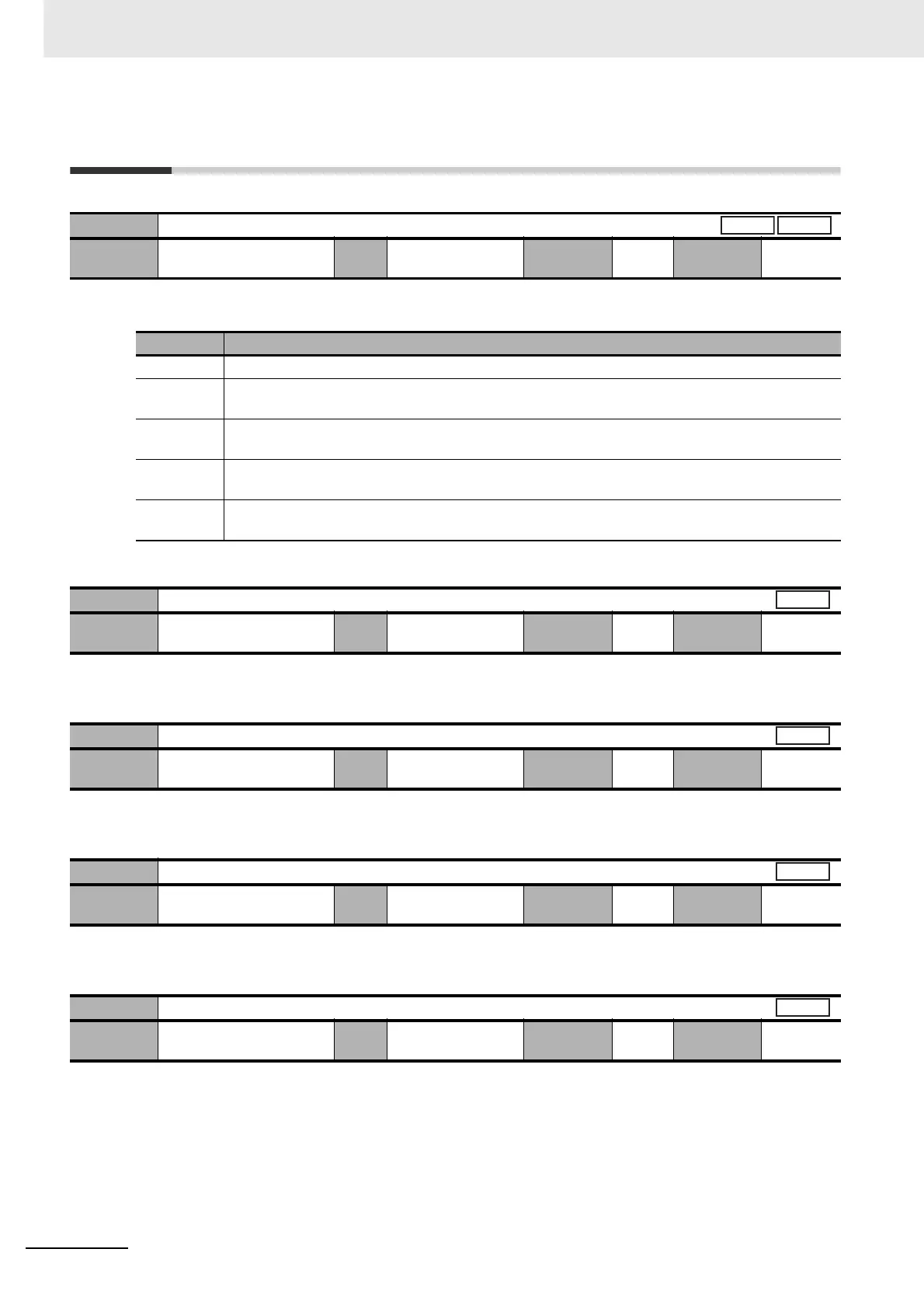
• Set the operation of the adaptive filter.
• Set the frequency of the first resonance suppression notch filter.
• When set to 5,000, the notch filter function is disabled.
• Set the width of the first resonance suppression notch filter in 20 levels.
• Increasing the setting value widens the notch width. Normally, use the default set value.
• Set the notch depth of the first resonance suppression notch filter.
• Increasing the setting value shortens the notch depth and the phase lag.
• Set the notch frequency of the second resonance suppression notch filter.
• When set to 5,000, the notch filter function is disabled.
Pn200
Adaptive Filter Selection
Setting
range
0 to 4 Unit – Default
setting
0
Cycle the
power supply
–
Set value Description
0 Disabled. The parameters related to notch filters 3 and 4 hold the current values.
1 One filter enabled. The parameters related to notch filter 3 are updated according to the adaptive
result.
2 Two filters enabled. The parameters related to notch filters 3 and 4 are updated according to the
adaptive result.
3 Resonance frequency measured. The measurement result can be checked in CX-Drive. The
parameters related to notch filters 3 and 4 hold the current values.
4 Adaptive result cleared. The parameters related to notch filters 3 and 4 are disabled and the
adaptive result is cleared.
Pn201
Notch 1 Frequency Setting
Setting
range
50 to 5,000 Unit Hz Default
setting
5,000
Cycle the
power supply
–
Pn202
Notch 1 Width Setting
Setting
range
0 to 20 Unit – Default
setting
2
Cycle the
power supply
–
Pn203
Notch 1 Depth Setting
Setting
range
0 to 99 Unit – Default
setting
0
Cycle the
power supply
–
Pn204
Notch 2 Frequency Setting
Setting
range
50 to 5,000 Unit Hz Default
setting
5,000
Cycle the
power supply
–
Position
Speed
All
All
All
All

 Loading...


