A - 11
Appendices
OMNUC G5-series (Pulse-train Input Type) AC Servomotors and Servo Drives User’s Manual
A-2 Parameter List
A
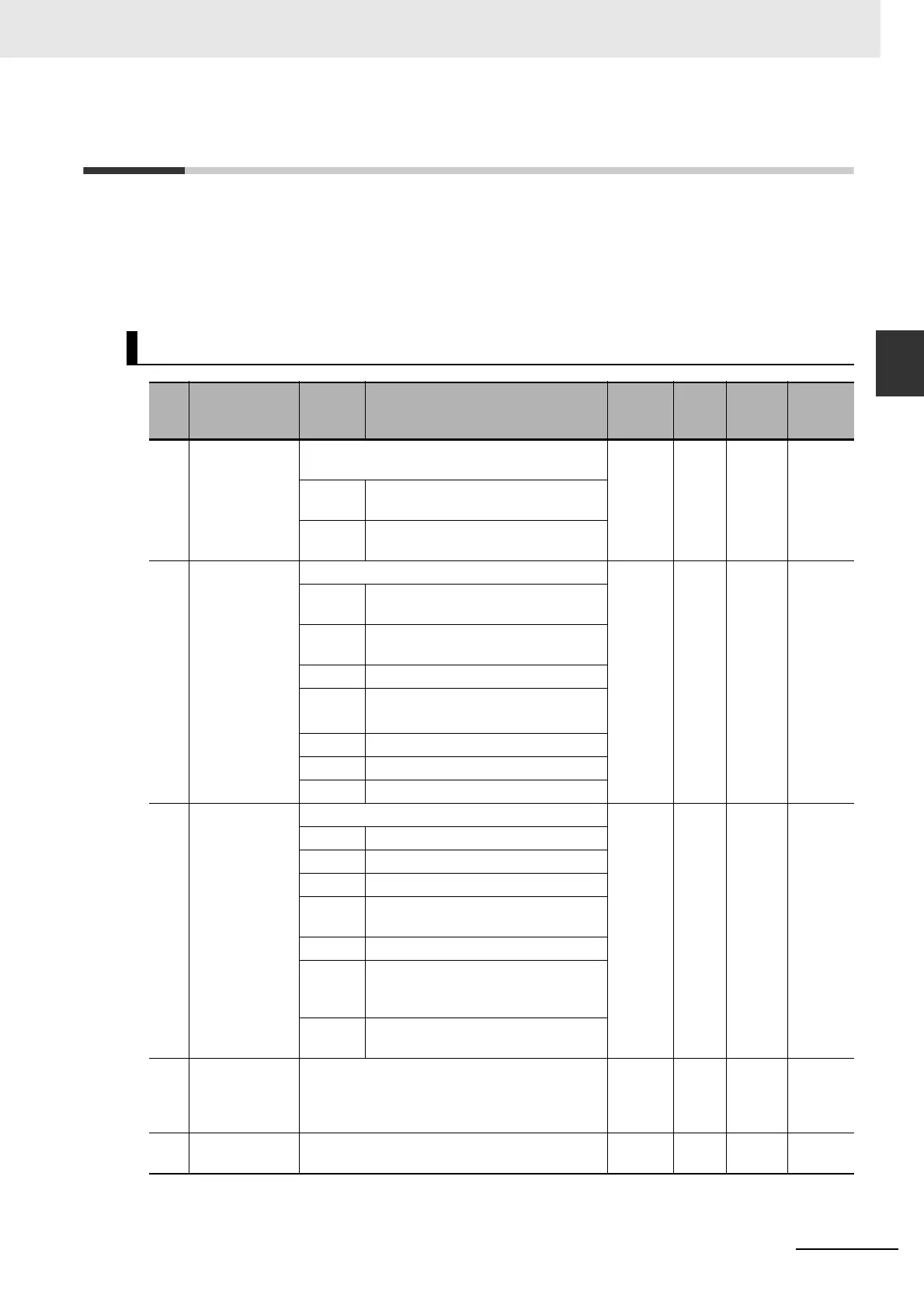
A-2 Parameter List
• Some parameters are enabled by cycling the power supply (shown in the tables below). After
changing these parameters, turn OFF the power supply, confirm that the power supply indicator is not
lit, and then turn ON the power supply again to restart the system.
• Do not change the parameters marked “Reserved.”
Do not change the set values marked “Not used” or “Reserved”.
Basic Setting Parameters
Pn
No.
Name Setting Description
Default
setting
Unit
Setting
range
Cycle the
power
supply
000 Rotation
Direction
Setting
Set the relation between the command direction
and the motor rotation direction.
1 – 0 to 1
Required
0 Forward (CW) when viewed from
shaft end for positive (+) commands
1 Reverse (CCW) when viewed from
shaft end for positive (+) commands
001 Control Mode
Selection
Select the control mode of the Servo Drive. 0 – 0 to 3
Required
0 Position control (Pulse-train
command)
1 Speed control (Internally set speed
control)
2 Reserved (Do not set.)
3 Mode 1: Position control
Mode 2: Speed control
4 Reserved (Do not set.)
5 Reserved (Do not set.)
6 Reserved (Do not set.)
002 Realtime
Autotuning
Mode Selection
Set the realtime autotuning operation mode. 1 – 0 to 6 –
0 Disabled
1 Focus on stability
2 Focus on position control
3 Used when an unbalanced load is
present on a vertical axis etc.
4 Used when friction is large
5 Used when an unbalanced load is
present on a vertical axis etc. and
friction is large
6 Used when customizing the realtime
autotuning function
003 Realtime
Autotuning
Machine
Rigidity Setting
Set the machine rigidity when realtime
autotuning is enabled.
13
*1
– 0 to 31 –
004 Inertia Ratio Set the load inertia as a percentage of the
motor rotor inertia.
250 % 0 to
10,000
–

 Loading...


