5 - 5
5 Basic Control Mode
OMNUC G5-series (Pulse-train Input Type) AC Servomotors and Servo Drives User’s Manual
5-1 Position Control
5
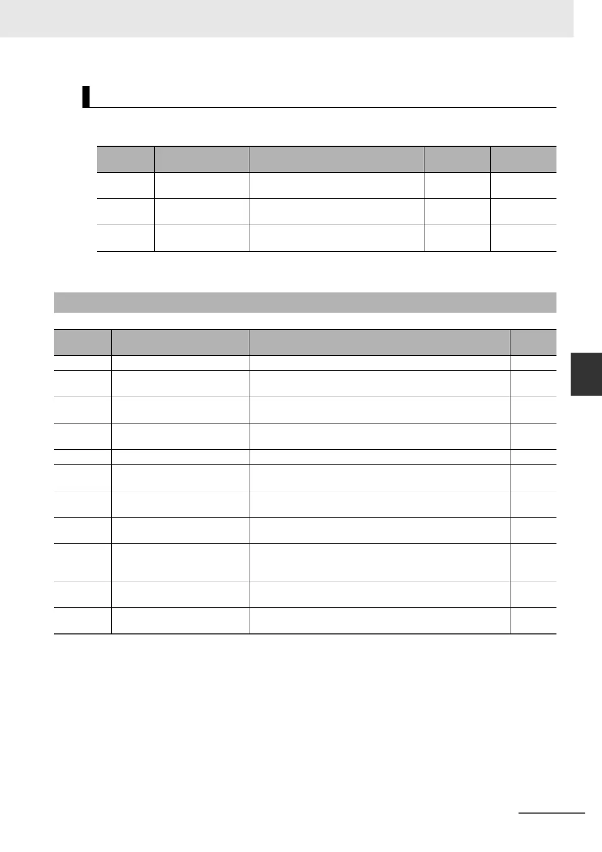
5-1-3 Related Functions
The electronic gear function enables to multiply the pulse command input from the host controller by the
specified gear ratio to determine the position command to the position control.
• For details about the electronic gear function, refer to 6-4 Electronic Gear Function on page 6-11.
Electronic Gear Function (Pn008, Pn009, Pn010)
Parameter
No.
Name Description
Setting
range
Unit
Pn008 Electronic Gear
Integer Setting
Set the number of command pulses per
motor rotation.
0 to 2
20
Pulse
Pn009 Electronic Gear Ratio
Numerator 1
Set the numerator of the electronic gear
ratio for the command pulse input.
0 to 2
30
–
Pn010 Electronic Gear Ratio
Denominator
Set the denominator of the electronic
gear ratio for the command pulse input.
1 to 2
30
–
5-1-3 Related Functions
Parameter
No.
Name Description
Reference
Pn008 Electronic Gear Integer Setting Set the number of command pulses per motor rotation. P.7-7
Pn011 Encoder Dividing Numerator Set the pulse output resolution using the numbers of output
pulses per rotation for phase A and phase B, respectively.
P. 7- 8
Pn012 Encoder Output Direction
Switching Selection
Set the combination of the phase-B logic and the output source
for pulse output.
P. 7- 8
Pn222 Position Command Filter Time
Constant
Set the time constant of the first-order lag filter for the position
command.
P.7-24
Pn223 Smoothing Filter Time Constant Set the time constant of the FIR filter for the position command. P.7-25
Pn431 Positioning Completion Range 1 Set the threshold for the position error at which the Positioning
Completion Signal is output.
P.7-37
Pn432 Positioning Completion
Condition Selection
Select the condition under which the Positioning Completion
Signal is output.
P.7-37
Pn433 Positioning Completion Hold
Time
Set the INP signal output duration. P.7-37
Pn503 Encoder Dividing Denominator Set the dividing ratio by using Encoder Dividing Numerator
(Pn011) as the dividing numerator and Encoder Dividing
Denominator (Pn503) as the dividing denominator.
P.7-42
Pn517 Error Counter Reset Condition
Selection
Set the condition for resetting the Error Counter Reset input
signal.
P.7-49
Pn518 Command Pulse Prohibition
Input Setting
Set whether to enable or disable the Command Pulse
Prohibition Input.
P.7-50

 Loading...


