6 Applied Functions
6 - 36
OMNUC G5-series (Pulse-train Input Type) AC Servomotors and Servo Drives User’s Manual
• The functions that are used by more than one control mode (such as Operation Command and
Alarm Reset Input) must be allocated to the same pin with the same logic. If they are not set
correctly, Interface Input Duplicate Allocation Error 1 (Alarm No. 33.0) or Interface Input
Duplicate Allocation Error 2 (Alarm No. 33.1) will occur.
• The Operation Command (RUN) must be allocated. Servo cannot be turned ON if it is not
allocated.
You can allocate any functions to the output pins of the control I/O connector (CN1).
If you replace a G-series Servo Drive, use the G5-series Servo Drive with the default settings.
The allocations of the default output signals are as follows. Refer to Output Signal Allocation Method on
page 6-37 when you change the allocation to use.
*1 Alarm output signal allocation cannot be changed.
Use the following parameters when changing the output signal allocations.
For the setting method, refer to Output Signal Allocation Method on page 6-37.
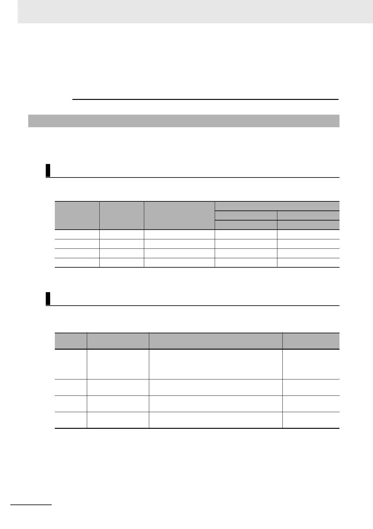
6-9-3 Output Signals
Default Output Signal Settings
Parameter
Output signal Default setting
Default setting state
Position control Speed control
Signal Signal
Pn410 SO1 00030303 hex (197379) BKIR BKIR
Pn411 SO2 00020202 hex (131586) READY READY
Pn412 SO3 *1 ALM ALM
Pn413 SO4 00050504 hex (328964) INP TGON
Parameters That can be Allocated
Parameter
No.
Name Description Reference
Pn410 Output Signal
Selection 1
Set the SO1 output function allocation. This
parameter must be set in hexadecimal notation. For
the setting method, refer to the Function Number
Table of output signals.
P.7-32
Pn411 Output Signal
Selection 2
Set the SO2 output function allocation. P.7-33
Pn412 Output Signal
Selection 3
Set the SO3 output function allocation. This
parameter is fixed to the alarm output signal.
P.7-33
Pn413 Output Signal
Selection 4
Set the SO4 output function allocation. P.7-33

 Loading...


