6 Applied Functions
6 - 46
OMNUC G5-series (Pulse-train Input Type) AC Servomotors and Servo Drives User’s Manual
6-14 Inertia Ratio Switching Function
You can switch between the inertia ratio 1 and 2 using Inertia Ratio Switching Input (JSEL). This
function is effective if it is used when the load inertia changes in 2 levels.
You can use the inertia ratio switching function in the following situations.
• The servo is ON.
• The Servomotor can rotate normally without any failures.
• The realtime autotuning function is disabled.
• The adaptive filter function is disabled.
• The instantaneous speed observer function is disabled.
• The disturbance observer function is disabled.
1
Set Function Expansion Setting (Pn610).
Set whether to enable or disable inertia ratio switching function in bit 3.
0: Disabled
1: Enabled
2
Set Inertia Ratio 1 (Pn004).
3
Set Inertia Ratio 2 (Pn613).
4
Set the Inertia Ratio Switching Input (JSEL) signal.
Precautions for Correct UsePrecautions for Correct Use
• Be sure to switch the inertia ratio with the Servomotor stopped.
• Vibration may occur even when the Servomotor is stopped if the values set in Inertia Ratio 1
and Inertia Ratio 2 differ significantly. Before using the Servomotor, check to be sure that the
vibration causes no problem.
6-14-1 Outline of the Function
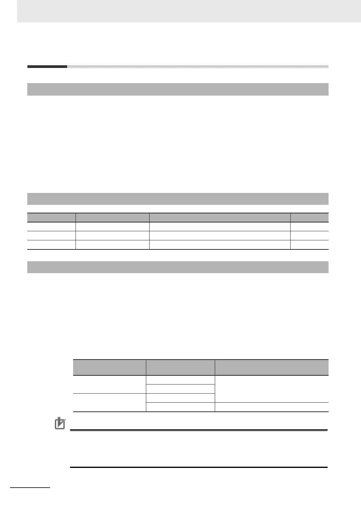
6-14-2 Parameters Requiring Settings
Parameter No. Name Description Reference
Pn610 Function Expansion Setting Set the bits related to the inertia ratio switching function. P.7-56
Pn004 Inertia Ratio 1 Set the first inertia ratio. P.7-4
Pn613 Inertia Ratio 2 Set the second inertia ratio. P.7-56
6-14-3 Operating Procedure
Function Expansion
Setting (Pn610)
Inertia Ratio Switching
Input (JSEL)
Applicable inertia ratio
bit 3 = 0: Inertia ratio
switching function disabled
OFF Inertia Ratio 1 (Pn004)
ON
bit 3 = 1: Inertia ratio
switching function enabled
OFF
ON Inertia Ratio 2 (Pn613)

 Loading...


