EasyManua.ls Logo

Omron G5 Series User Manual

Omron G5 Series
506 pages
To Next Page IconTo Next Page
To Previous Page IconTo Previous Page
Page #162 background image
3 Specifications
3 - 62
OMNUC G5-series (Pulse-train Input Type) AC Servomotors and Servo Drives User’s Manual
3-5 Cable and Connector Specifications
The specifications of the cables that connect the Servo Drive with a Servomotor are shown below. The
information on the connectors is also provided.
Select an appropriate cable for the Servomotor.
If the cable is used in a moving environment, use a global flexible cable.
Regarding the bending life of a global flexible cable, a wire rod with a durability of more than 20 million
times of use at or above the minimum bending radius is used under the conditions below.
Precautions for Correct UsePrecautions for Correct Use
Because the life expectancy data on resistance to bending is intended for reference only, use
the cable with a sufficient margin.
The durability of more than 20 million times of use refers to the number of times which the core
conductor provides electrical continuity without causing cracks and scratches that can have
functional impact on the sheath, which does not cover the disconnection of shielded wire.
Malfunction or grounding fault due to dielectric breakdown may occur if cables are used at a
radius smaller than the minimum bending radius.
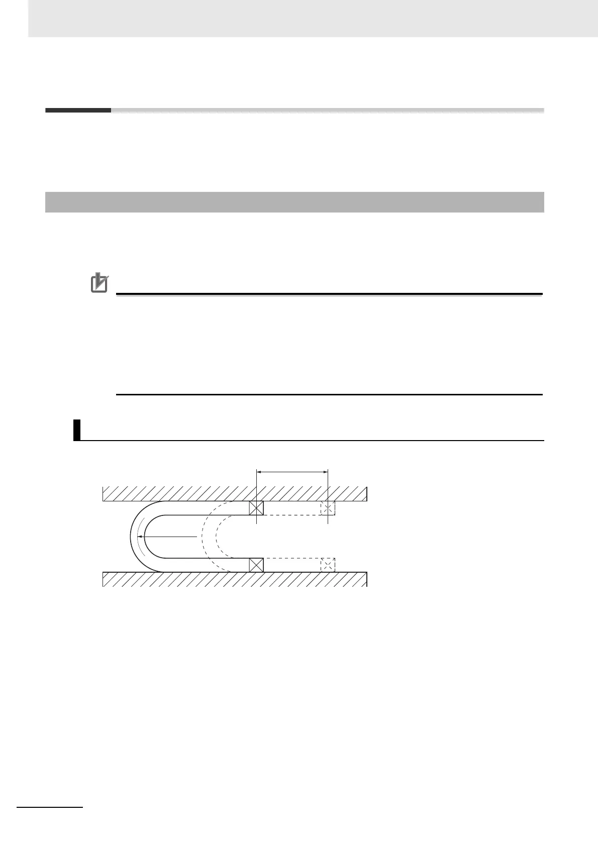
3-5-1 Resistance to Bending of Global Flexible Cable
Moving Bend Test
Stroke
750 mm
Bending
radius (R)
30 times/min

Table of Contents

Other manuals for Omron G5 Series

Questions and Answers:

Omron G5 Series Specifications

General IconGeneral
FeedbackIncremental Encoder, Absolute Encoder
CommunicationEtherCAT
Safety FunctionSTO (Safe Torque Off)
Protection FunctionsOvervoltage, Undervoltage, Overcurrent
Vibration Resistance4.9 m/s² (10 to 55 Hz)

Summary

AC Servomotors/Servo Drives G5-series

Read and Understand this Manual

Warranty and Limitations of Liability

Details OMRON's product warranty, limitations of liability, and disclaimers regarding product use and damages.

Application Considerations

Suitability for Use

OMR ON's disclaimer on product conformity to standards and suitability for specific applications.

Safety Precautions

Explanation of Displays

Explains the meaning of DANGER and Caution displays for hazardous situations.

Explanation of Symbols

Defines symbols used for danger, prohibition, and compulsory actions.

Installation and Wiring

Operation and Adjustment

Manual Configuration

Section 1 Features and System Configuration

Section 2 Models and External Dimensions

Section 3 Specifications

3-1 Servo Drive Specifications

Details general specifications, characteristics, and international standards for Servo Drives.

3-3 Servomotor Specifications

Lists general specifications, characteristics, and international standards for Servomotors.

System Design

4-1 Installation Conditions

Guidelines for installing Servo Drives, Servomotors, and Decelerators, covering space, environment, and mounting.

4-2 Wiring

Explains peripheral equipment connection examples and main circuit/motor connections.

4-3 Wiring Conforming to EMC Directives

Details requirements for wiring to ensure EMC Directive conformance, including noise reduction measures.

Basic Control Mode

5-1 Position Control

Explains the outline of position control, parameters, related functions, and block diagrams.

5-2 Internally Set Speed Control

Details the outline of internally set speed control, required parameters, and operation examples.

Applied Functions

6-6 Brake Interlock

Explains the brake interlock function for controlling the holding brake timing and operation.

Section 7 Parameter Details

7-1 Basic Parameters

Details fundamental parameters like rotation direction, control mode, realtime autotuning, inertia ratio, and command pulse settings.

7-2 Gain Parameters

Covers parameters for adjusting position loop gain, speed loop gain, and their integral time constants for optimal servo system performance.

Section 8 Operation

8-1 Operational Procedure

Outlines the sequence of steps for correct installation, wiring, function settings, trial operation, and adjustment.

8-2 Preparing for Operation

Lists essential items to check before turning ON the power supply, including voltage, wiring, and connections.

8-5 Trial Operation

Details inspections and procedures for performing trial operation to confirm servo system functionality.

Section 9 Adjustment Functions

9-1 Gain Adjustment

Explains the purpose and methods of gain adjustment, including realtime autotuning and manual tuning.

9-2 Realtime Autotuning

Describes the realtime autotuning process for estimating load inertia and automatically setting gain, including conditions for proper operation.

Section 10 Troubleshooting and Maintenance

10-1 Actions for Problems

Outlines preliminary checks and analytical methods to determine the cause of problems and take appropriate measures.

10-3 Alarm List

Details alarm codes, error detection functions, descriptions, causes, and measures for troubleshooting.

10-4 Troubleshooting

Guides on diagnosing errors based on alarm displays and operation states, providing probable causes and measures.

Appendices

Related product manuals