3 - 27
3 Specifications
OMNUC G5-series (Pulse-train Input Type) AC Servomotors and Servo Drives User’s Manual
3-1 Servo Drive Specifications
3
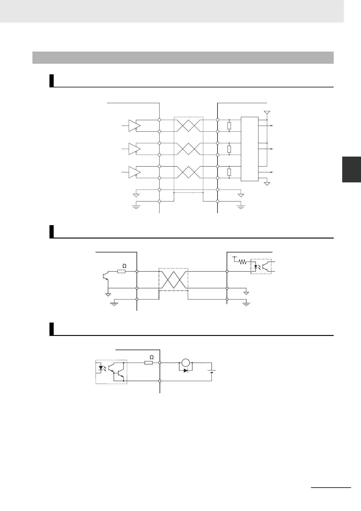
3-1-7 Control Output Circuits
3-1-7 Control Output Circuits
Position Feedback Output
Phase-Z Output (Open Collector Output)
Sequence Output
ControllerServo Drive
+A21
–A22
+B49
–B48
+Z23
–Z24
SGGND
25
FGShell
+A
–A
+B
–B
+Z
–Z
GND
Phase A
Phase B
Phase Z
Output line driver
M26C31 or equivalent
FG
0 V
R = 120 to 180 Ω
R
R
R
FG
0 V
0 V
+5 V
Phase A
Phase B
Phase Z
Applicable line receiver
AM26C32 or equivalent
SGGND
Z19
25
FG
Shell
Servo Drive Controller
0 V
FGFG
10
Maximum service
voltage: 30 VDC max.
Maximum output
current: 50 mA max.
–
X
Di
+
Servo Drive
10
External power supply
12 to 24 VDC
Maximum service voltage: 30 VDC max.
Maximum output current: 50 mA max.
Di: Surge voltage prevention diode
(When driving a relay directly with an output
signal, always insert a diode as shown in the
above figure. Use a high-speed diode.)

 Loading...


