3 Specifications
3 - 32
OMNUC G5-series (Pulse-train Input Type) AC Servomotors and Servo Drives User’s Manual
No allocation: Speed Command Status Output (V-CMD)
No allocation: Speed Command Status Output Common (V-CMDCOM)
This is the default allocation. The allocation of output terminals (CN1 pin 10, 11, 34, 35, 38 and 39) can
be changed using Output Signal Selection 1 to 4 (Pn410 to Pn413).
Function
This output signal turns ON when a speed command is input in the speed control mode.
Connectors for CN2 (6 Pins)
Speed Command Status Output (V-CMD)
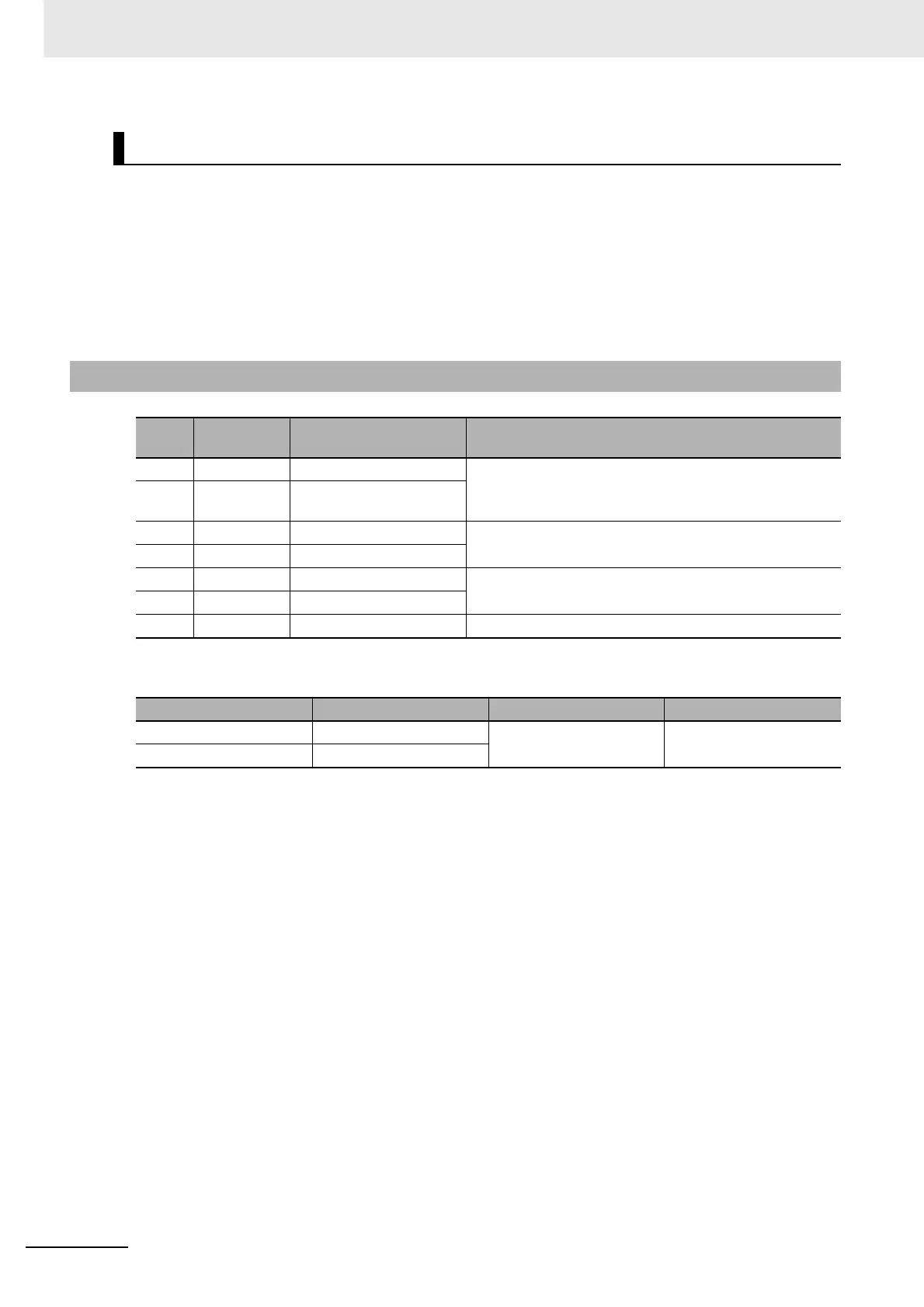
3-1-9 Encoder Connector Specifications (CN2)
Pin
No.
Symbol Name Function and interface
1E5V
Encoder power supply +5 V
Power supply output for the encoder
2 E0V Encoder power supply
GND
3 – Not used Do not connect.
4–Not used
5 PS+ Encoder + phase-S input Encoder signal I/O (Serial signal)
6 PS– Encoder – phase-S input
Shell FG Frame ground Frame ground
Name Model Manufacturer OMRON model number
Drive connector 53460-0629 Molex Japan R88A-CNW01R
Cable connector 55100-0670

 Loading...


