LD Cart Transporter User's Guide, 14766-000 Rev B
Page 126 of 190
Chapter 7: Operator Interface
Light Disc Beacon Meaning
Color Pattern Color Pattern
Green/White
arc
Partial Circle/-
moving small arc
Green normally, Red
if E-Stopped
Blink Charging
Red Blink Red Blink E-Stop, stops driving
Blue Left+Right
Half-circles
Green/Yellow/Red Alt Booting
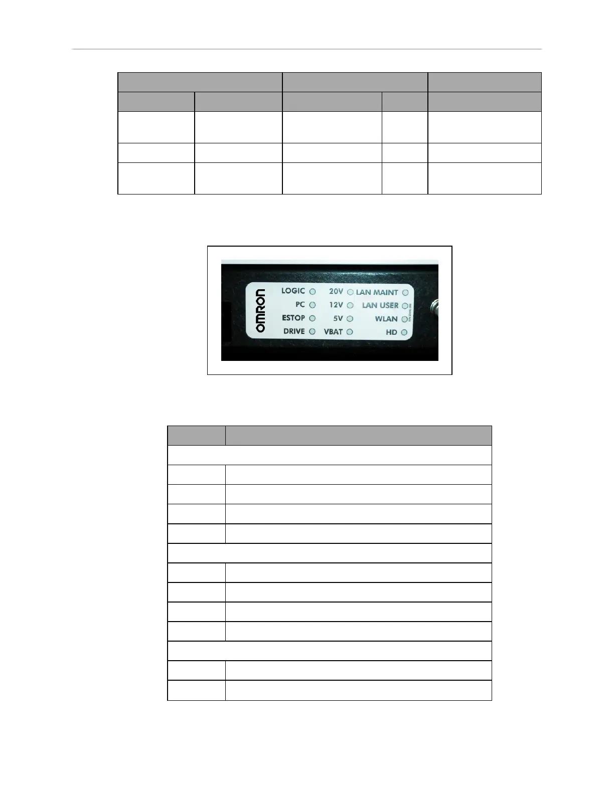
Robot Core Indicators
The left end of the robot core has 12 indicator lights.
Figure 7-15. Core Indicator Lights
The following table gives their meanings:
Indicator Meaning
Left Column
LOGIC The microcontroller has power
PC The robot core and the servo controller are communicating
DRIVE The drive wheels are under servo control
ESTOP An E-Stop has been activated
Middle Column
20V 20 V power is available
12V 12 V power is available
5V 5 V power is available
VBAT Raw battery power is available
Right Column
LANMAINT The Maintenance Ethernet connector is showing activity
LANUSER The USER LAN connector is showing activity
 Loading...


