LD Cart Transporter User's Guide, 14766-000 Rev B
Page 97 of 190
Chapter 6: Connectivity
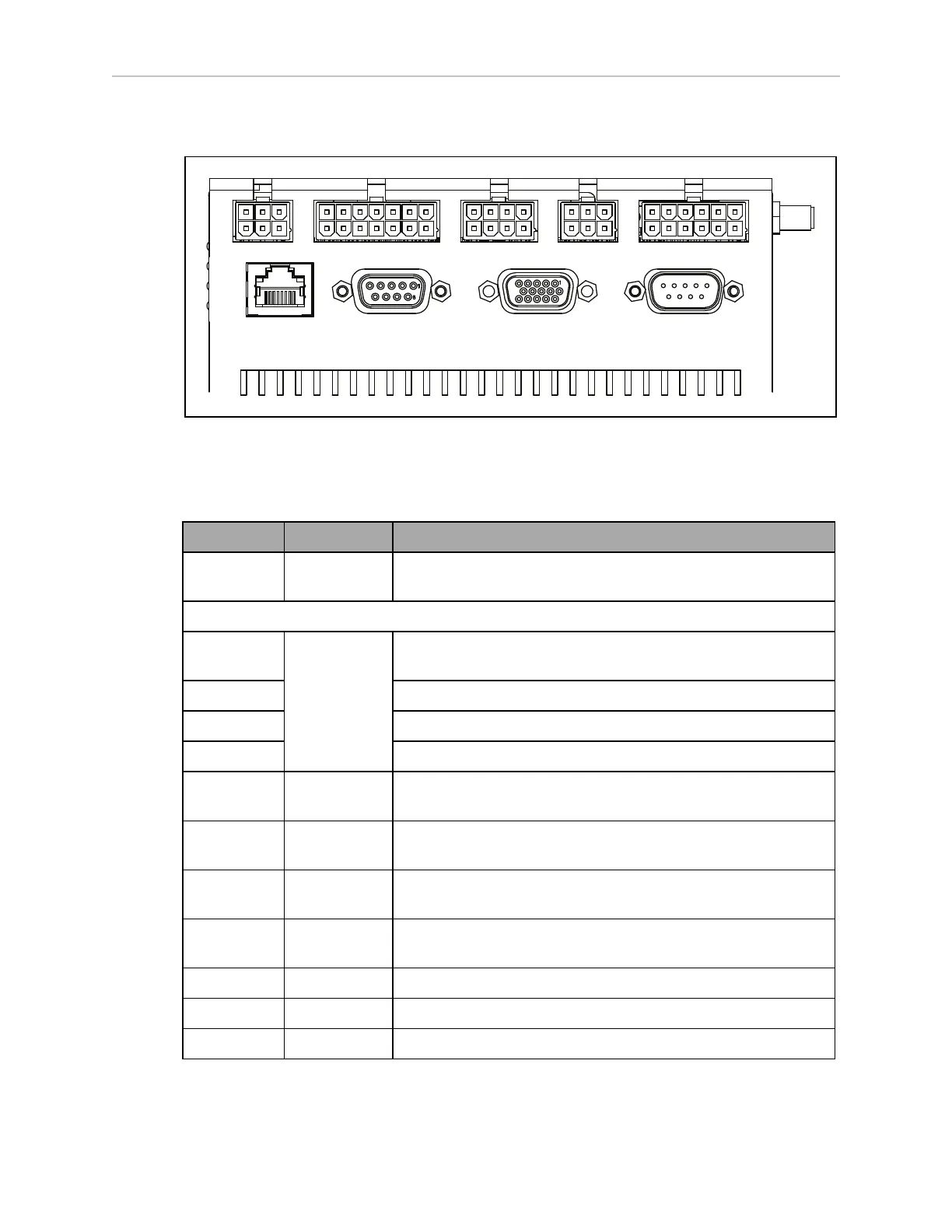
Robot Core Rear, Upper
Light Pole User Interface User Bumpers Aux Power User Power
Maint LAN Joystick HMI Panel Sonar 2
Figure 6-8. Rear Upper Core
NOTE:The connectors in the top row of the Rear Upper Core mate with Molex
Mini-Fit Jr™ 5557 series receptacles.
Connection Type Description
Light Pole Mini-Fit 2 x 3 Connects to a user-supplied light tower with 3 lights and 1
buzzer, using a default configuration
NOTE:The following four functions are pins on the User Interface connector.
Brake-
release
Mini-Fit 2 x 7 Pins for user-supplied brake release
ON Pins for user-supplied ON button
OFF Pins for user-supplied OFF button
ESTOP Pins for user-supplied E-Stop (must be used or jumpered)
User
Bumpers
Mini-Fit
2 x 4
This connection is not used with a cart transporter.
Aux Power Mini-Fit
2 x 3
5, 12, and 20 VDC Outputs
User Power Mini-Fit
2 x 6
Battery and switched battery power
Maint LAN RJ45,
Shielded
Directly connected to the externally-mounted Maintenance
Ethernet, Auto-MDIX.
Joystick DB9F Directly connected to the externally-mounted Joystick port
HMI Panel HDB15F Operator screen, E-Stop, Brake_Rel, ON, OFF
Sonar 2 DB9M This connection is not used with a cart transporter.
 Loading...


