LD Cart Transporter User's Guide, 14766-000 Rev B
Page 90 of 190
Chapter 6: Connectivity
NOTE:If a connection is in Connectivity on page 83, it means that the description
here does not apply to the transporter, because that connection is being used for a
cart-specific use.
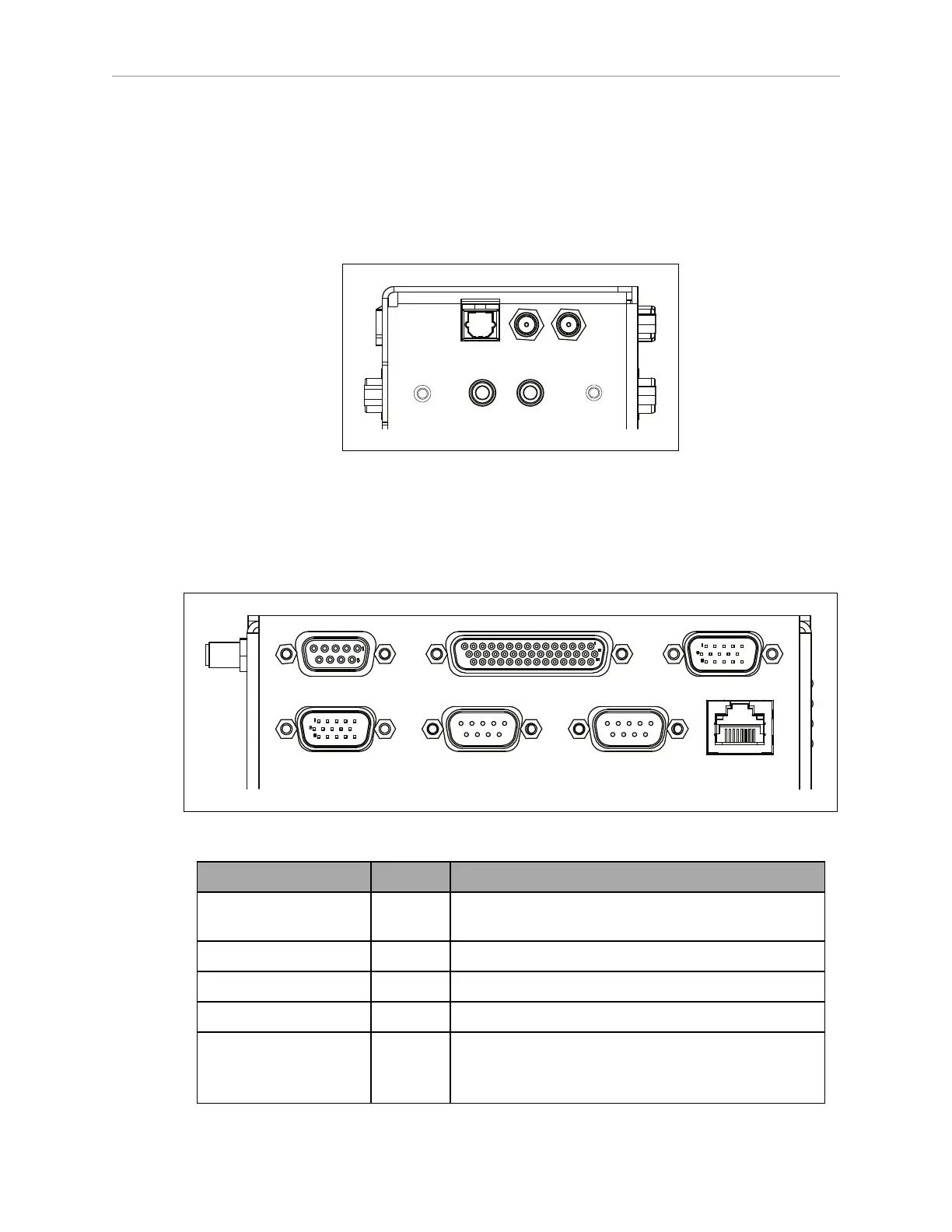
NOTE:Standard connectors, such as audio, are not covered here. These are on the
right side of the core, shown in the following figure:
Digital
Ant1
Ant2
Audio In
Audio Out
Audio Out
Figure 6-4. Right Side of the Core
The left end of the robot core has 12 indicator lights. Their meanings are covered in Robot Core
Indicators on page 126.
Robot Core Front, Upper
CAN Bus B Digital I/O
Analog I/O
User LANRS232-1RS232-2Aux Sensors
Figure 6-5. Front Upper Core
Connection Type Description
User LAN RJ45,
Shielded
General Ethernet, Auto-MDIX.
Aux Sensors HDB15M Side lasers
RS-232 x 2 DB9M Port 1 and Port 2, general use
CAN Bus B DB9F Consult Support for use.
Digital I/O (HDB44F) HDB44F 16 digital inputs, in 4 banks of 4. Each bank can be
wired as active high or active low depending on the
connection of the BANK# terminal.
 Loading...


