EasyManuals Logo
Home>Omron>Touch terminals>NT31

Omron NT31 Setup Manual

Omron NT31
313 pages
To Next Page IconTo Next Page
To Previous Page IconTo Previous Page
Page #103 background imageLoading...
Page #103 background image
86
Connecting to the Host’s RS-232C Port Section 5-1
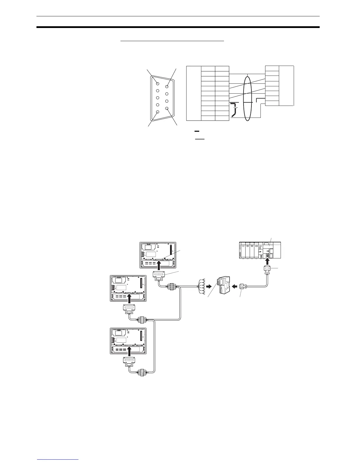
Wiring for a Memory Link Connection
Prepare the adapter cable while referring to the diagram shown below.
Since it is necessary to input a voltage of +5 V to the number 6 pin of NT-
AL001, supplying a voltage of 5 V from the host or an external voltage supply
for NT-AL001 is required.
5-1-3 1:N Connection between RS-422A/485 at the PT and RS-232C at
the Host
The connection method in which the RS-422A/485 ports of multiple NT31/
NT31Cs are connected to the RS-232C port of one host in a 1:N connection is
described here.
An RS-232C/RS-422A Adapter (NT-AL001) is used to convert between the
RS-232C and RS-422A/485 communications methods.
(9-pin type)
Shielding wire
No +5 V output is at the host side
A +5 V out
p
ut is
p
resent at the host side
NT-AL001 side
Host side
1
6
5
9
FG
−
SD
RD
RS
CS
+5V
−
−
SG
1
2
3
4
5
6
7
8
9
SD
RD
RS
CS
(+5V)
SG
Abbreviation
Abbreviation
Pin number
Connector
hood
RS-232C
connector
RS-232C
connector
Connector
hood
NT31/NT31C
Host Link Unit/CPU Unit
25-pin connector
9-pin connector
9-pin connector
Max. 2 m
Relay terminal block
Serial port B
(RS-422A/485,
25-pin type)
RS-422A terminal
block
RS-232C cable with
connectors
RS-232C/RS-422A
convertor unit
(NT-AL001)
CS/CJ-series PLC,
C200HX/HG/HE(-Z)E
RS-422A/485 cable
(max. total length: 500 m)

Table of Contents

Other manuals for Omron NT31

Questions and Answers:

Question and Answer IconNeed help?

Do you have a question about the Omron NT31 and is the answer not in the manual?

Omron NT31 Specifications

General IconGeneral
BrandOmron
ModelNT31
CategoryTouch terminals
LanguageEnglish

Related product manuals