121
Connecting to the Host’s RS-422A/485 Port Section 5-2
For details on handling shield wires, refer to 5-2-8 Handling the Shield on RS-
422A/485 Cables on page 128.
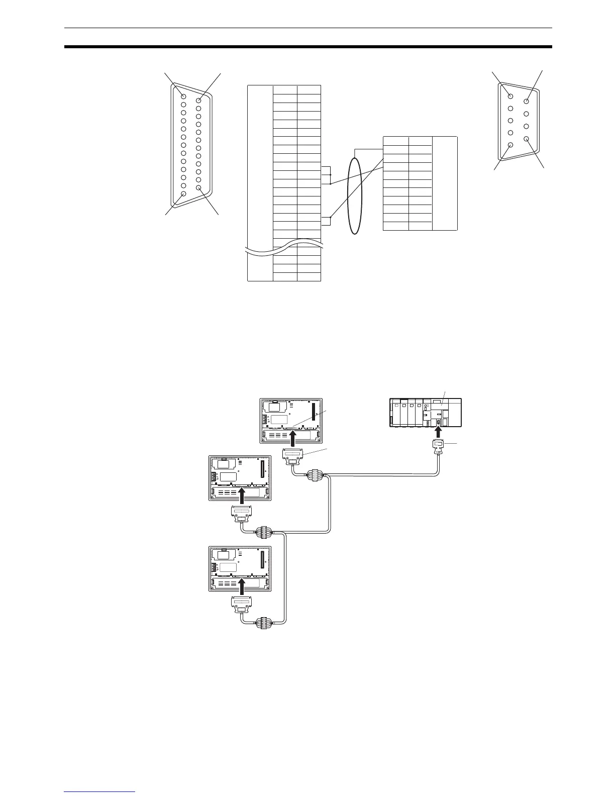
5-2-4 1:N Connection among RS-422A Ports
The connection method in which the RS-422A ports of multiple NT31/NT31Cs
and one host are connected in a 1:N connection is described here.
Reference: • Communications using the RS-422A standard NT link (1:N) method is
possible only when a Serial Communications Board (CS Series only) or
Serial Communications Unit is installed in a CS/CJ-series PLC, a Com-
munications Board is installed in a C200HX/HG/HE(-Z)E, or a CQM1H-
SCB41 Serial Communications Board is installed in a CQM1H.
1
14
13 25
Shielding wire
6
5
9
1
NT31/NT31C side
(25-pin type)
Abbreviation
FG
−
SD
RD
RS
CS
−
SG
−
TRM
RDB (+)
SDB (+)
−
−
−
SDA (-)
RDA (-)
−
−
RSB (+)
RSA (-)
−
Pin number
1
2
3
4
5
6
7
8
9
10
11
12
13
14
15
16
−
23
24
25
RS-232C/
422A/485
connector
Connector
hood
−
(9-pin type)
FG
SDA (-)
SDB (+)
−
−
−
RDA (-)
−
RDB (+)
−
1
2
3
4
5
6
7
8
9
Abbreviation
Pin number
Connector
hood
RS-422A
connector
PLC (CPU Unit) side
NT31/NT31C
25-pin connector
9-pin connector
CPU Unit
24V
DC
PRINTERPORT B
Max. 2 m
Relay terminal block
Serial port B
(RS-422A, 25-pin
type)
RS-422A cables
(max. total length 500 m)
CS/CJ-series,
C200HX/HG/HE(-Z)E,
CQM1H PLC

 Loading...


