126
Connecting to the Host’s RS-422A/485 Port Section 5-2
Note A Serial Communications Board cannot be used.
For details on handling shield wires, refer to 5-2-8 Handling the Shield on RS-
422A/485 Cables on page 128.
5-2-6 Recommended Connectors, Cables and Crimp Terminals
Connectors and Cables Recommended for RS-422A/485
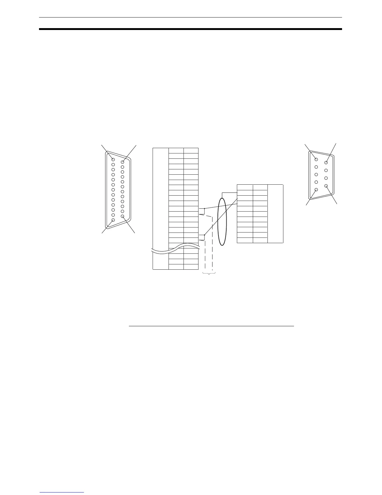
When making an RS-422A/485 connecting cable, as far as possible use the
recommended parts indicated in the table below. When using the memory link
method, however, use a connector that matches with the RS-422A port at the
CPU Unit (CP). Some Units come supplied with one connector and connector
hood.
CS1G-CPU42/43/44/45-E(V1)
CS1H-CPU63/64/65/66/67-E(V1)
CS1G-CPU42H/43H/44H/45H
CS1H-CPU63H/64H/65H/66H/67H
CS1D-CPU65H/67H (See note.)
C200HE-CPU32/42-(Z)E
C200HG-CPU33/43/53/63-(Z)E
C200HX-CPU34/44/54/64-(Z)E
C200HX-CPU65-ZE/85-ZE
CQM1H-CPU51/61
141
13 25
Shielding wire
6
5
9
1
Next PT
NT31/NT31C side
(25-pin type)
Abbreviation
FG
−
SD
RD
RS
CS
−
SG
−
TRM
RDB (+)
SDB (+)
−
−
−
SDA (-)
RDA (-)
−
−
RSB (+)
RSA (-)
−
Pin number
1
2
3
4
5
6
7
8
9
10
11
12
13
14
15
16
−
23
24
25
RS-232C/
422A/485
connector
Connector
hood
−
(9-pin type)
FG
SDA (-)
SDB (+)
−
−
−
RDA (-)
−
RDB (+)
−
1
2
3
4
5
6
7
8
9
Abbreviation
Pin number
Connector
hood
RS-422A
connector
PLC (CPU Unit) side

 Loading...


