94
Connecting to the Host’s RS-422A/485 Port Section 5-2
Note Before connecting or disconnecting cables between devices, make sure that
the power supply to all of the connected devices (NT31/NT31C, PLC, etc.) is
OFF.
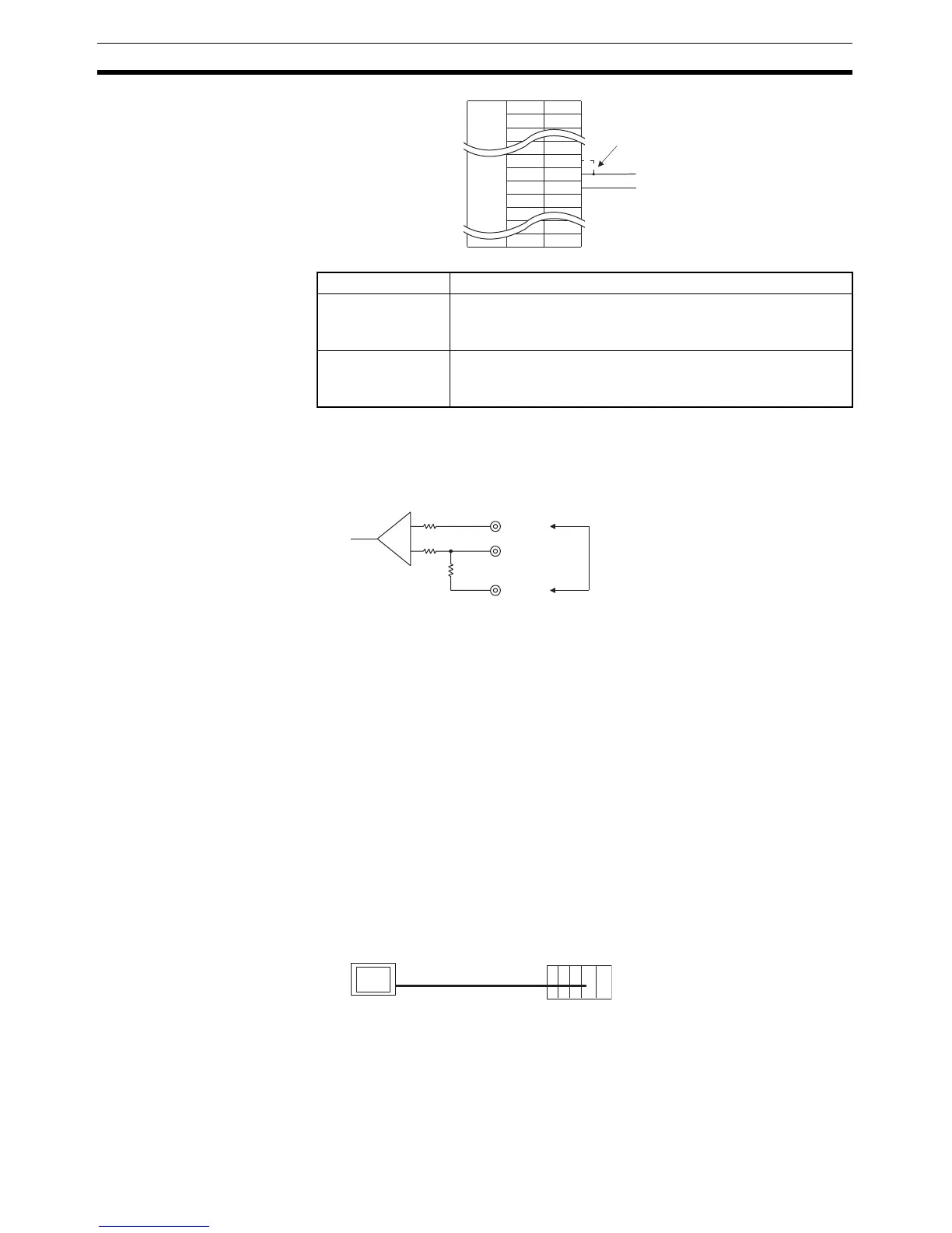
Reference: • The internal circuit of the NT31/NT31C is shown below.
• For details on setting the terminal resistance of NT-AL001-E, refer to Set-
tings at the RS-232C/RS-422A Adapter (NT-AL001-E) (page 81).
5-2 Connecting to the Host’s RS-422A/485 Port
The methods for connecting the RS-422A/485 port of the NT31/NT31C and
the RS-422A/485 port of the host are described here. There are the following
methods.
The following discussion is focused on the connection method to OMRON
PLCs (By using the memory link method, a connection can be made to any
arbitrary RS-422 unit). When making a connection to a host other than
OMRON PLCs, refer to the PLC Connection Manual (V042-E1-@) or Multi
Vendor Connection Manual (V060-E1-@).
• Method in which the RS-422A ports of the NT31/NT31C and host are
connected directly by an RS-422A cable (page 116).
When this method is used, the cable length can be extended up to 500 m.
• Method in which the RS-485 ports of the NT31/NT31C and host are con-
nected by an RS-485 cable (page 119).
When this method is used, the cable length can be extended up to
500 m.
Pin Nos. 9 and 10 Function
Shorted Terminal resistance is applied.
Short only at the NT31/NT31C connected to the end of an RS-
422A/485 cable.
Open Terminal resistance is not applied.
Leave the terminals open when connecting an NT31/NT31C
anywhere other than at the end of the RS-422A/485 cable.
Abbreviation
FG
-
-
TRM
RDB (+)
SDB (+)
-
-
-
Pin number
-
9
10
11
12
-
25
Terminal resistor setting
Connector
hood
-
-
-
16 (RDA)
9 (TRM)
10 (RDB)
+
−
Terminal resistor (120 Ω)
Making a connection here inserts
a terminator between + (RDB)
and - (RDA).
PT Host
RS-422A cable

 Loading...


