243
Maintenance of the NT31/NT31C Section 7-3
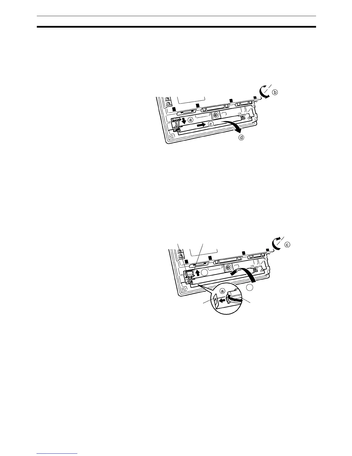
b. Sufficiently loosen the screw that secures the CFL unit.
The screw is designed so that it cannot be removed, but if it does come
out for some reason and falls inside the PT, it must be extricated with-
out fail.
c. Shift the CFL unit to the right.
d. Pull out the CFL unit.
5. Fit a new CFL unit by following the procedure described below.
a. Slot the projection on the left end of the CFL unit into the hole in the
fixture inside the PT.
b. Engage the CFL unit with the fixture inside the PT.
Check that the CFL unit is in contact with the left end of the fixture and
is parallel with the fixture during this engagement.
c. Tighten the screw of the CFL unit to secure it.
The tightening torque is 0.2 N
⋅m.
d. Engage the connector of the CFL unit with the connector of the PT so
that the red cable is at the left side.
Insert the connector so that it clicks firmly into place.
6. Fit the cover and secure it with the screw.
7. Reconnect the wiring, cables, and units disconnected in 2, and tighten the
screws.
8. Before starting normal operation, confirm that the following tests can be
executed correctly by using the I/O check in the Maintenance menu. Also
perform a communications test with the host.
• Touch switch
•Backlight
9. On confirming that all the tests in 8 can be executed normally, start opera-
tion.
7-3-1 Replacing the Battery
The NT31/NT31C uses a lithium battery to back up the memory contents.
Backlight unit
Red cable
White cable
b
d
Fixture inside the
NT31-ST121@-EV2/NT31C-ST
141@-EV2

 Loading...


