119
Connecting to the Host’s RS-422A/485 Port Section 5-2
For details on handling shield wires, refer to 5-2-8 Handling the Shield on RS-
422A/485 Cables on page 128.
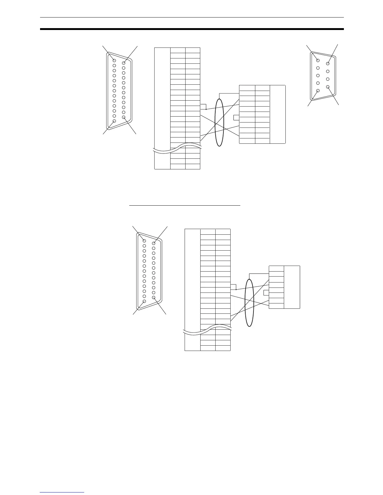
Wiring for a Memory Link Connection
Prepare the adapter cable while referring to the following diagram.
For details on handling shield wires, refer to 5-2-8 Handling the Shield on RS-
422A/485 Cables on page 128.
5-2-3 Direct Connection between RS-485 Ports at Both Units
The connection method in which the RS-485 ports of an NT31/NT31C and a
host are connected is described here.
1
14
13 25
Shielding wire
6
5
9
1
NT31/NT31C side
(25-pin type)
Abbreviation
FG
−
SD
RD
RS
CS
−
SG
−
TRM
RDB (+)
SDB (+)
−
−
−
SDA (-)
RDA (-)
−
−
RSB (+)
RSA (-)
−
Pin number
1
2
3
4
5
6
7
8
9
10
11
12
13
14
15
16
−
23
24
25
RS-232C/
422A/485
connector
Connector
hood
−
(9-pin type)
FG
SDA
SDB
−
RS
CS
RDA
−
RDB
−
1
2
3
4
5
6
7
8
9
Abbreviation
Pin number
Connector
hood
RS-422A
connector
PLC (CPU Unit) side
1
14
13 25
Shielding wire
NT31/NT31C side
(25-pin type)
Abbreviation
FG
−
SD
RD
RS
CS
−
SG
−
TRM
RDB (+)
SDB (+)
−
−
−
SDA (-)
RDA (-)
−
−
RSB (+)
RSA (-)
−
Pin number
1
2
3
4
5
6
7
8
9
10
11
12
13
14
15
16
−
23
24
25
RS-232C/
422A/485
connector
Connector
hood
−
Host side
SDA
SDB
RS
CS
ROA
ROB
Abbreviation
RS-422A
connector
Connector
hood

 Loading...


