128
Connecting to the Host’s RS-422A/485 Port Section 5-2
Note Before connecting or disconnecting cables between devices, make sure that
the power supply to all of the connected devices (NT31/NT31C, PLC, etc.) is
OFF.
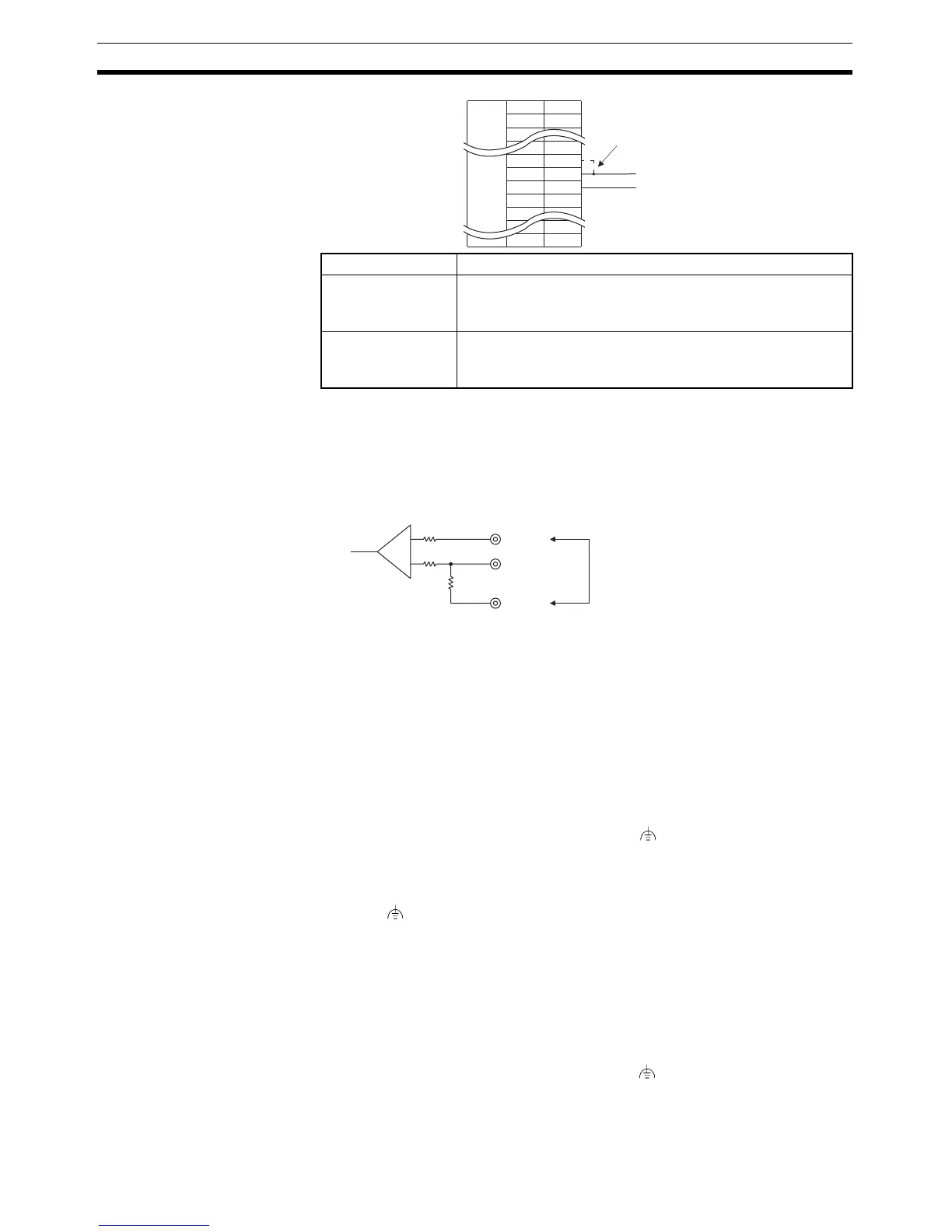
Reference: • The internal circuit of the NT31/NT31C is shown below.
• For details on setting the terminal resistance of the host, refer to setting
methods for each type of the communications.
5-2-8 Handling the Shield on RS-422A/485 Cables
Perform the following procedures to connect, process the shield, and connect
to ground for communications systems using the RS-422A/485. Incorrect con-
nection may result in communications errors with the host.
Connecting the Ground Wire
The PT has a functional ground terminal (FG: ).
1,2,3... 1. Ground according to Figure (a) for normal grounding.
• Connect the ground terminal (GR) of the devices to the functional ground
(FG: ).
Make sure that each signal line is grounded at only one point and ground
to 100
Ω max.
• Short the LG terminal of the PLC to the ground terminal (GR).
• Use a wire gauge of at least 2mm
2
for the ground wire.
• Refer to the manual for individual Communications Units for details on
proper wiring procedures.
2. Do not ground the functional ground (FG: ) of the PT if it is mounted to
the same panel as devices that generate noise, such as motors or invert-
ers, as shown in Figure (b).
Pin Nos. 9 and 10 Function
Shorted Terminal resistance is applied.
Short only at the NT31/NT31C connected to the end of an RS-
422A/485 cable.
Open Terminal resistance is not applied.
Leave the terminals open when connecting an NT31/NT31C
anywhere other than at the end of the RS-422A/485 cable.
Abbreviation
FG
-
-
TRM
RDB (+)
SDB (+)
-
-
-
Pin number
-
9
10
11
12
-
25
Terminal resistor setting
-
-
-
Connector
hood
16 (RDA)
9 (TRM)
10 (RDB)
+
−
Terminal resistor (120 Ω)
Making a connection here inserts
a terminator between + (RDB)
and - (RDA).

 Loading...


