13 Maintenance and Inspection
13 - 2
AC Servomotors/Servo Drives 1S-series with Built-in EtherCAT® Communications User’s Manual (I586)
13-1 Periodic Maintenance
Servomotors and Servo Drives contain many components and will operate properly only when each of
the individual components is operating properly.
Some of the electrical and mechanical components require maintenance depending on application con-
ditions. Periodic inspection and replacement are necessary to ensure proper long-term operation of
Servomotors and Servo Drives. (Quoted from The Recommendation for Periodic Maintenance of a
General-purpose Inverter published by JEMA.)
The periodic maintenance cycle depends on the installation environment and application conditions of
the Servomotors and Servo Drives.
Recommended maintenance times are given below for Servomotors and Servo Drives. Use these for
reference in periodic maintenance.
Note AC-type fuses are built in a Servo Drive at 5.5 kW or more. Even when one of the fuses blows due to a fail-
ure of a rectifier diode in the Servo Drive, in some cases, Main Circuit Power Supply Phase Loss Error
(Error No.13.01) does not occur and the Servo Drive operates. That causes shortening of parts life of the
Servo Drive. Therefore, measure the conductivity of the terminals between L1-P and L3-P with a tester
(diode mode), referring to 1-4 System Block Diagram on page 1-21, and Check that the fuse does not blow.
If the fuse has a failure, replace the Servo Drive.
Check Procedure
1 Cut off a power supply of a Servo Drive, and start the check after the following time pass.
10 minutes: R88D-1SN55F-ECT, R88D-1SN75F-ECT, R88D-1SN150F-ECT
20 minutes: R88D-1SN55H-ECT, R88D-1SN75H-ECT, R88D-1SN150H-ECT
2 Disconnect wiring from a main circuit connector of the Servo Drive or a main circuit terminal
block (CNA).
3 Set a tester to diode mode. Check conductivity between terminals, following the below table.
Display depends on a tester.
Tester terminal (+) Tester terminal (-)
Display on the tester
in normal
Display on the tester in normal
Display on the tester when
fuse blows
L1 P 1 V max. Non-conductivity (O.L.)
L3 P 1 V max. Non-conductivity (O.L.)
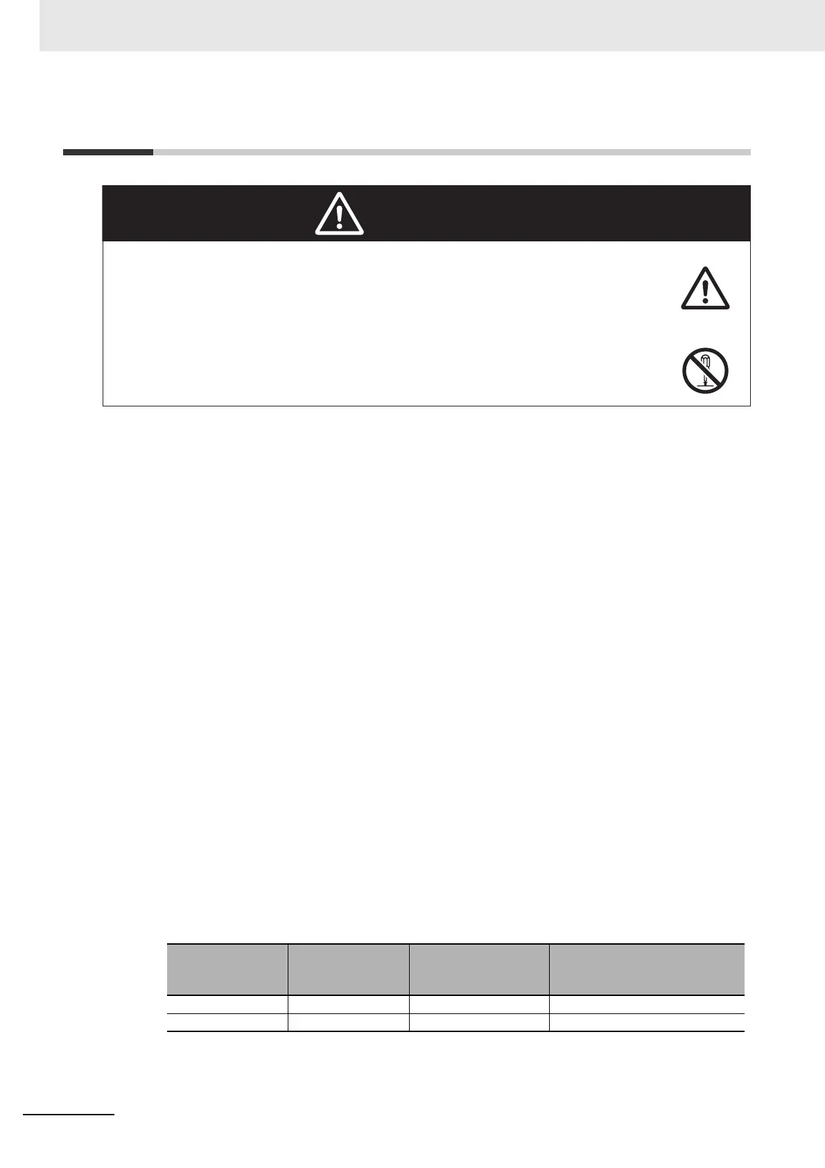
Caution
After replacing the Servo Drive, transfer to the new Servo Drive
all data needed to resume operation, before restarting operation.
Equipment damage may result.
Do not repair the Servo Drive by disassembling it.
Electric shock or injury may result.

 Loading...

