PCX SMS AND PCX 256 SYSTEM MANUAL
RINS871-3 Page: 113
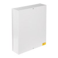
CHAPTER 16: THE RADIO EXPANDER
The radio expander contains the 868 inovonics receiver and programming PCB. To connect the expander to
the PCX system please see page 114. A total of 10 radio expanders can be connected to the PCX 256
system, and a total of 2 to the PCX 26/SMS system.
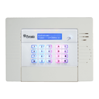
16.1 The Radio Expander
The display is 2 x 7 segments and there are 4 control buttons:
‘AZ’ = Assign zones/repeaters
‘MO’ = EOL mode or ID mode
‘CLEAR’ = Clear Information
‘ENTER’ = Accept Information
D
1
-
T
X
R
E
S
E
T
S
E
R
I
A
L
M
F
F
A
D
2
+
V
s
D
3
G
N
D
D
4
R
X
TAMPER
AZ
MO
CLEAR
ENTER
RESET
FAULT
88
A total of 7 detectors can be programmed using the End of Line mode on a radio expander, and 29 can be
programmed using the ID mode.
The ‘OK’ and ‘FAULT’ LEDs relate to the RS485 connection to the PCX system.
NOTE: The last input on the expander should be programmed as ‘Fault’ with the name ‘RF Low
Battery’ to indicate a detector low battery problem. If an RF Low Battery is reported then the radio
expander will show on the display the number of the detector with the low battery: e.g.
Lb…21
.
Supervision failure will be reported as ‘tamper’ on the relevant input.
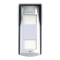
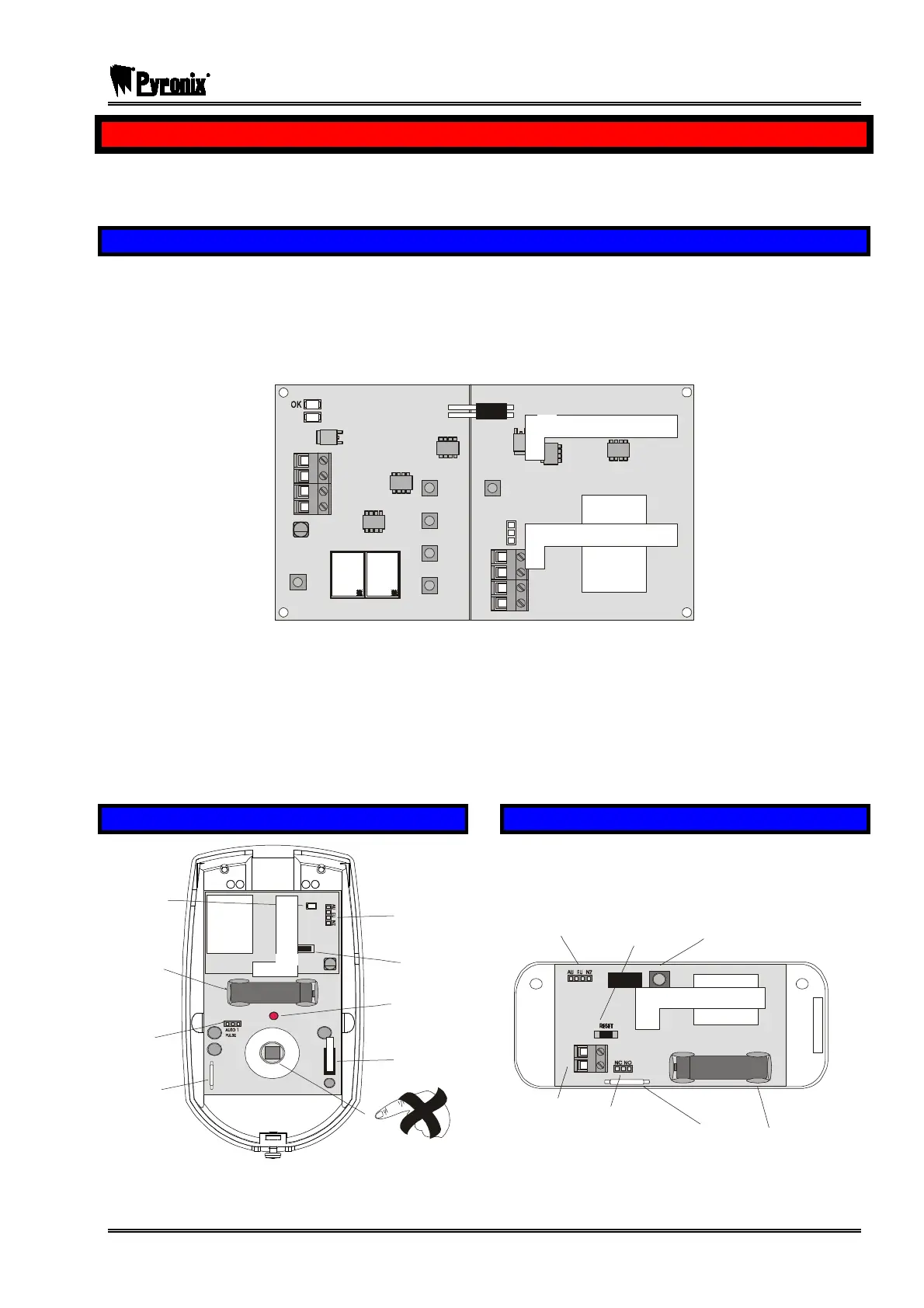
16.2 The Radio PIR Detector
+
-
Pyro Sensor
Communication
LED
PIR LED
RESET Button
Battery
Sensitivity
Setting
Magnet
Tamp e r Swit c h
Frequency Pins
(Must be on EU)
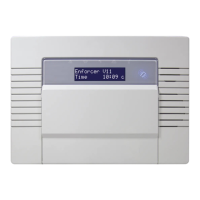
16.3 The Radio Door Contact
Reset Button
Tamper Button
Battery
Magnet
Normally Closed /
Normally Open
Contact
External
Contacts
Frequency Pins
(Must be on EU)
+

 Loading...