PCX SMS AND PCX 256 SYSTEM MANUAL
RINS871-3 Page: 137
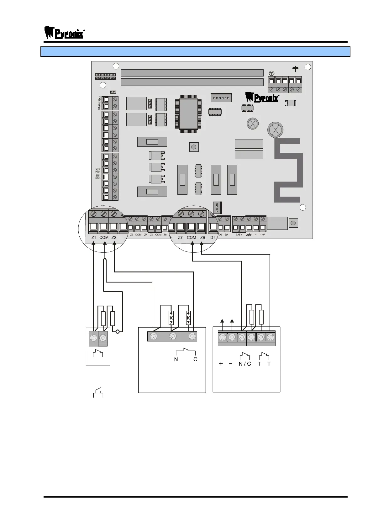
17.13.5 Configuration of Shunt Inputs
NC1
COMMS PGMS
TAMP ER
RESET
ENGINEER
KEYPAD
RS232
BATTERY
CONNECT
----------------SAB----------------
COMMUN ICATION CARD
EXPANSION CARD SLOT
AUX+
C1
SPK
NO1
NC2
-1 B-1 A B
C2
TR
NO2
B-
B+
F2
F3 F4 F5
F1
PGMS
BELL
AUX
BUS
BATTERY
4
K
7
4
K
7
4
7
K
4
7
K
SUPPLY
ALARM TAMPER
Input 8
+AUX-
Spare
ALARM
Shunt 1
Detector assigned
to Shunt 1
Detector assigned
to Shunt 1
Input 2
N/O
N/C
(Normally Open can be
selected in Input Attributes)
In this example, Inputs 2 and 8 have been programmed as 24 hour inputs, and are assigned to Shunt 1.
When input 1 (programmed as ‘Shunt Input’) is opened, after 10 seconds, Inputs 2 and 8 become active.
If Input 1 hasn’t been activated, Inputs 2 and 8 are disabled.
To program this feature, please see page: 52.

 Loading...