PCX SMS AND PCX 256 SYSTEM MANUAL
Page: 116 RINS871-3
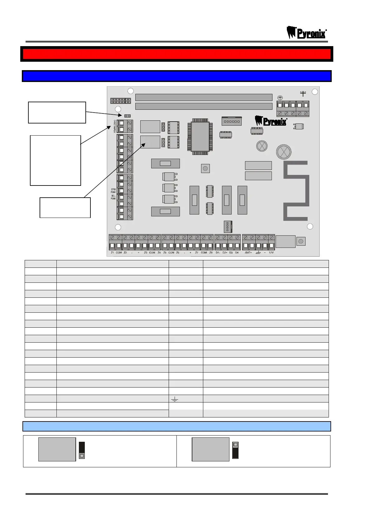
CHAPTER 17: WIRING DIAGRAMS
17.1 PCX 26/SMS and PCX 256 Printed Circuit Board Layout
NC1
COMMS PGMS
TAMPER
RESET
ENGINEER
KEYPAD
RS232
BATTERY
CONNECT
----------------SAB----------------
COMMUNICATION CARD
EXPANSION CARD SLOT
AUX+
C1
SPK
NO1
NC2
-1 B-1 A B
C2
TR
NO2
B-
B+
F2
F3 F4 F5
F1
PGMS
BELL
AUX
BUS
BATTERY
NO1
PGM 1 Relay Normally Closed Output
Z5
Programmable Input 5
C1
PGM 1 Relay Common Output
COM
Input Common
NC1
PGM 1 Relay Normally Open Output
Z6
Programmable Input 6
NO2
PGM 2 Relay Normally Closed Output
Z7
Programmable Input 7
C2
PGM 2 Relay Common Output
COM
Input Common
NC2
PGM 2 Relay Normally Open Output
Z8
Programmable Input 8
AUX+
Auxiliary Supply
D1
RS485 0V Supply
SPK
Speaker (Dedicated output)
D2
RS485 +12V Supply
PGM4
PGM 4 Output (Strobe)
D3
RS485 ‘A’ Data
PGM5
PGM 5 Output (Bell)
D4
RS485 ‘B’ Data
TR
Bell Tamper
-BAT
Battery Negative Terminal
B-
Auxiliary 0V Supply
BAT+
Battery Positive Terminal
B+
Auxiliary +12V Supply
GND
Earth
Z1
Programmable Input 1
17V~
17V AC Supply
COM
Input Common
A
For Connection to Telephone Network
Z2
Programmable Input 2
B
For Connection to Telephone Network
-
Auxiliary 0V Supply
A-1
For connection to other tel equipment
+
Auxiliary +12V Supply
B-1
For connection to other tel equipment
Z3
Programmable Input 3
Telephone Earth
COM
Input Common
CASE Do not wire circuits into these terminals
Z4
Programmable Input 4
TAMPER On UK installations
17.1.1 Relay Terminals:
Relay
If the jumper is on the
top two pins then the
relay is positive.
Relay
If the jumper is on the
bottom two pins then the
relay is negative.
Without the jumpers on the pins the relays are voltage free and if operated will need ‘C1’ and ‘C2’ linked to a
negative.
Case tamper
switch header
Do not wire
circuits into
these
terminals on
UK
installations
Relays
See below

 Loading...