PG-FP5 CHAPTER 1 OVERVIEW
R20UT0008EJ0400 Rev. 4.00 Page 13 of 240
Jul 15, 2010
Select the microcontroller to be used in the Each Device Series column and select the device name in the
Device Name column; the FP5 parameter file can then be found.
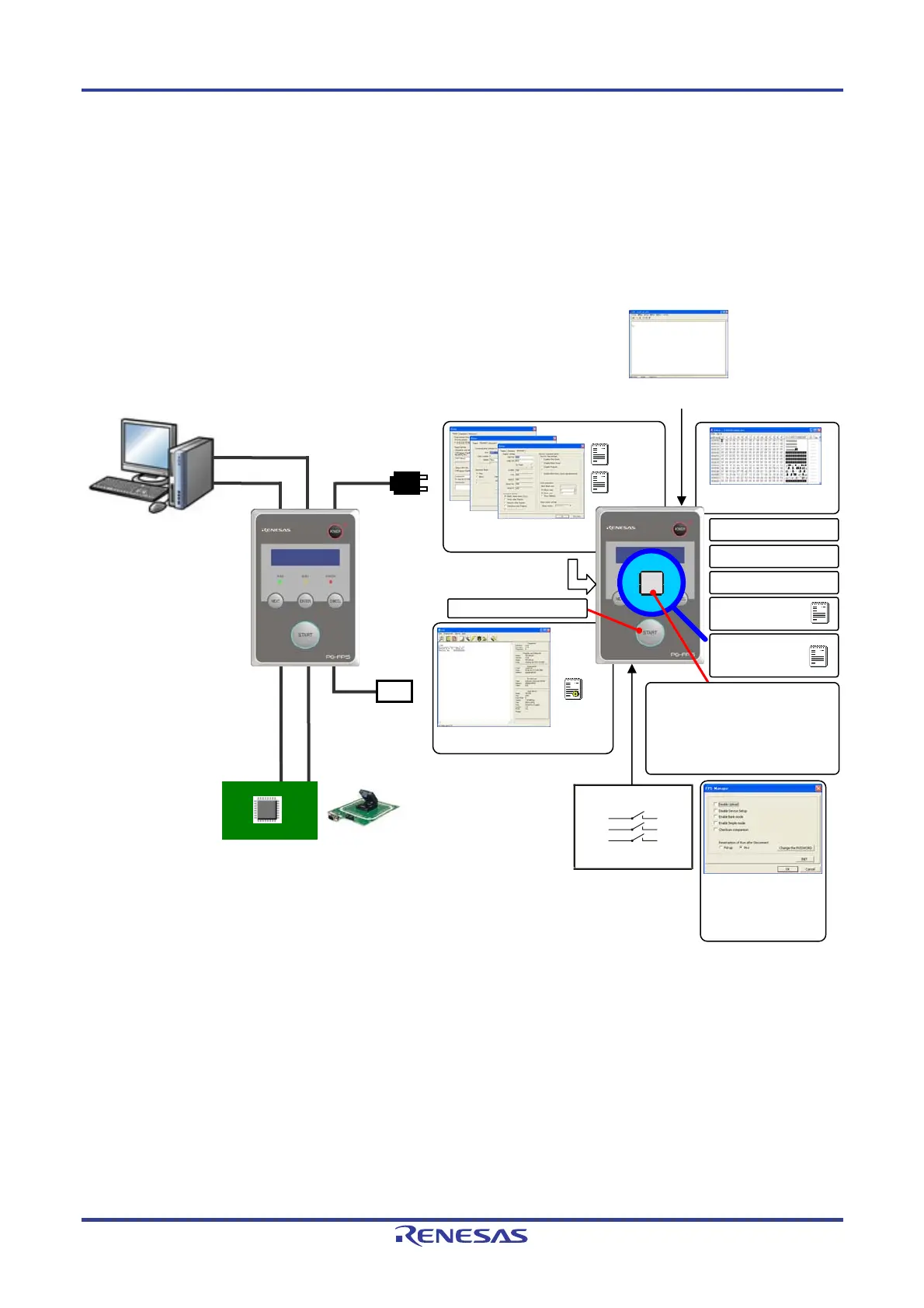
1.4 FP5 System Overview
The FP5 system overview is shown in the following diagrams.
Figure 1-1. FP5 Connection Image
PR5 file
ESF file
Programming
environment setting
Saving log files
Target cable
Serial cable
AC adapter
GND cable
Target system or program adapter
Saved in FP5 internal
flash memory
HEX editor changes
the memory contents
16MB
Checksum calculation
Built-in 16 MB flash memory for
saving program files
Files are divided by 4, in 4 MB
units or divided by 8, in 2 MB
units
Standalone operation
Downloading
program files
INI file
Programming GUI operation
Self-testing function
Buzzer function
USB cable
or
Communications
command operation
External control
devices
Remote Operation
Manager function
(passwords, security,
customization, etc.)
setting

 Loading...


