PG-FP5 CHAPTER 8 USAGE COMMUNICATION COMMANDS
R20UT0008EJ0400 Rev. 4.00 Page 155 of 240
Jul 15, 2010
8.4.11 lod command
Downloads program files.
Input format
'lod' ('add') ('fname="filename"') ('ftime="date and time"')
Description of the function
Downloads the program file to a valid programming area. After this command is executed, the program file must be
downloaded to the FP5 in ASCII format using communications software. If using HyperTerminal, select Transfer(T) ->
Transfer text file(T)..., and then select the program file. The options are to delete or not to delete the file before
downloading, the file name, and the creation date. If this command is executed without any options, then the file name
and creation date will not be stored.
add
Select this not to delete the data in the valid programming area before downloading program files. When this is
not designated, the data will be deleted. Please use this option when downloading and writing two program files.
Usually, this is not designated.
Note When this option is enabled and the lod command is executed, the PG-FP5 downloads data 512 bytes at
a time without erasing its internal flash memory. Note, however, that the download error “ERROR: NAND
flash – Illegal Write (Bit 0->1)” occurs if there is data other than FFh in the data being downloaded.
fname = “filename”
Designates the file name of the program file that is downloaded. The maximum number of characters is 31.
ftime = “date and time”
Designates the creation date and time of the downloaded program file. The format is YYYY-MM-DD HH:MM.
YYYY: Year; MM: Month; DD: Date; HH: Hour; MM: Minute
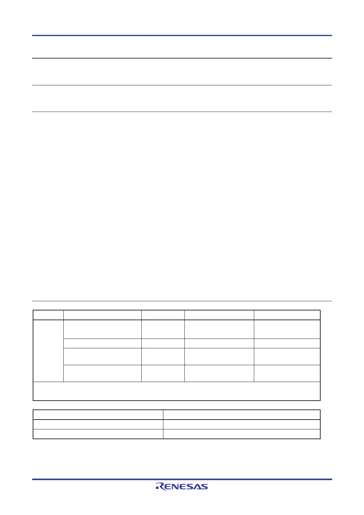
Example of usage
Command Status Status LED Message display Screen output
Display after execution of the
command (before downloading)
BUSY *** BUSY *** Preparing storage ....PASS
Now loading...
Display during downloading BUSY *** BUSY *** ...
Display after normal ending of the
download
PASS
Returns to the display before
executing the command.
PASS
lod
Display after error ending of the
download
ERROR
Returns to the display before
executing the command.
ERROR: <text>
Address range: 0x000000 to 0x007FFF, CRC32: 0x61D5F67C
PASS
Command Operation
lod fname="sample.hex" ftime="2006-02-24 21:13" Same operation as lod
lod add Same operation as lod