PG-FP5 CHAPTER 2 HARDWARE CONFIGURATION
R20UT0008EJ0400 Rev. 4.00 Page 22 of 240
Jul 15, 2010
2.3 Names and Functions on Main Unit
This section describes the names and functions on the FP5 main unit.
2.3.1 FP5 control panel
Indicators and buttons are laid out on the FP5 top.
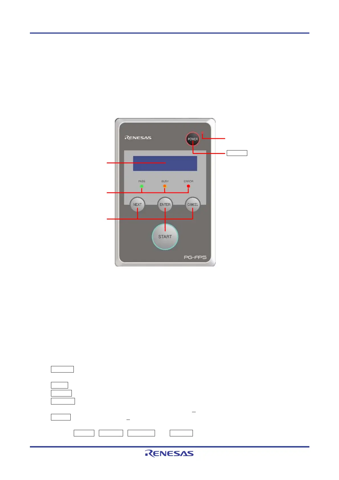
Figure 2-2. FP5 Top View <Control Panel>
(1) Indicators
• POWER LED LED that displays the FP5 power status.
A red LED is turned on when the FP5 is ON, and is turned off when the FP5 is OFF.
• Message display An LCD display of 16 × 2-characters that indicates the operating mode or menus.
It is mainly used when the FP5 operates in standalone mode.
• Status LEDs LEDs that show the FP5 operating status.
PASS (green LED turned on) indicates normal completion, BUSY (orange LED flashes)
indicates processing in progress, and ERROR (red LED turned on) indicates abnormal
completion.
(2) Buttons
• POWER button Used to turn on/off the power to the FP5. Press this button longer (for about 1 minute) when
turning on/off.
• NEXT button Proceeds to the next menu item at the same level in sequence.
• ENTER button Selects the item shown in the message display.
• CANCEL button Cancels the current selection and returns to the previous menu item. The command currently
running cannot be stopped, except for the [Read] command.
• START button Executes the [A
utoprocedure(E.P.)] command with a valid programming area setting.
Remark The NEXT , ENTER , CANCEL and START buttons are mainly used in standalone mode.
When the FP5 Manager is used to switch to the bank mode or simple mode, the button functions and
Control buttons
Status LEDs
Message display
POWER button
POWER LED

 Loading...


