PG-FP5 APPENDIX D ELECTRICAL SPECIFICATIONS OF REMOTE INTERFACE
R20UT0008EJ0400 Rev. 4.00 Page 231 of 240
Jul 15, 2010
(2/2)
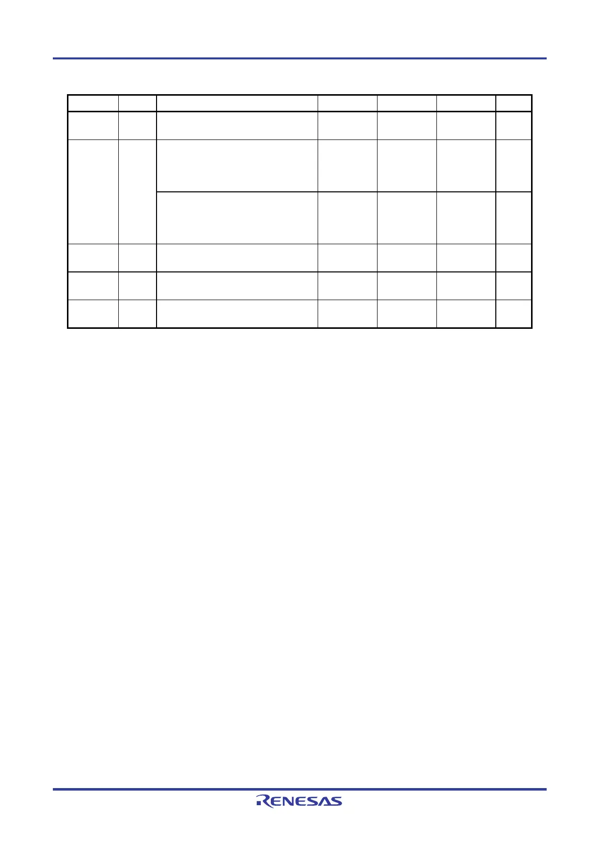
Pin name Symbol Parameter or Conditions MIN. TYP. MAX. Unit
tPBAIN
Time from the fall of the NEXT signal until
the VRF or START signal can be input
1 ms
Time from the fall of the VRF, START or
ENTER signal until the rise of the BUSY
signal (When the input signal is input after
having changed the program area)
5 ms
tPINBU
Time from the fall of the VRF, START or
ENTER signal until the rise of the BUSY
signal (When the input signal is input
without changing the program area)
50 ms
tPBUIN
Time from the fall of the BUSY signal until
the CLEAR signal can be input
1 ms
tPCLPE
Time from the fall of the CLEAR signal until
the fall of the PASS or ERROR signal
50 ms
tPPENE
Time from the fall of the PASS or ERROR
signal until the NEXT signal can be input
1 ms

 Loading...


