Installation
Transport System Installation
196 MagneMotion
Rockwell Automation Publication MMI-UM007F-EN-P - September 2020
Ethernet Motor Communications
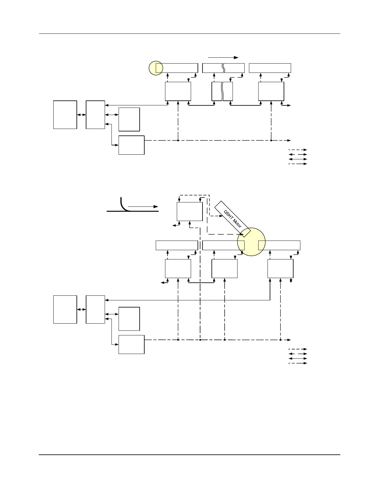
Figure 5-8: Simplified Representation of Ethernet Motor Connections
Figure 5-9: Simplified Representation of Ethernet Motor Connections in a Merge Switch
Installing Motor and Ethernet Motor Drive Communication Cables
When using the QSHT 5700 inverters, the QSHT motors can use different network style con-
nection schemes depending on the application. See Ethernet Motor Communication Recom-
mendations on page 79 and Ethernet Motor Connection Examples on page 80. The following
procedure provides steps for connecting the motors as shown in the simplified wiring dia-
grams in Figure 5-8 and Figure 5-9.
Simple QSHT Motor
Host
Controller
QSHT Motor
Enet
Switch
HLC &
Node
Controller
Power
To Next Motor
Controller in Path
Upstream Downstream
To Next Motor
Controller in Path
Downstream
QSHT 5700
Inverter
QSHT 5700
Inverter
Ethernet
2198-Pxxx
Power
Supply
Power
Drive
Sense
Ethernet
Merge
Host
Controller
Enet
Switch
Upstream Downs tream
From Previous Motor
Inverter in Path
Upstream
Switch Configuration
Downstream
To Next Motor
Inverter in Path
QSHT Motor QSHT Motor QSHT Motor
Power
To Next Motor
Controller in Path
From Previous Motor
Inverter in Path
Ethernet
QSHT 5700
Inverter
QSHT 5700
Inverter
QSHT 5700
Inverter
QSHT 5700
Inverter
HLC &
Node
Controller
2198-Pxxx
Power
Supply
Power
Drive
Sense
Ethernet
 Loading...

