Installation
Transport System Installation
QuickStick HT User Manual 203
Rockwell Automation Publication MMI-UM007F-EN-P - September 2020
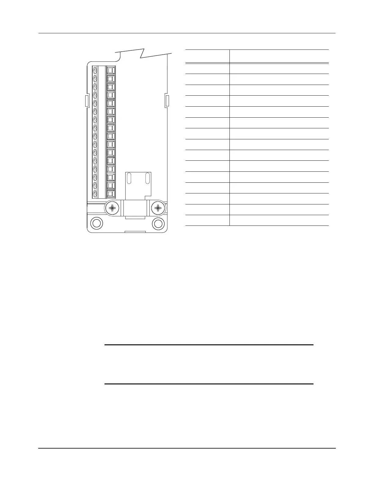
Figure 5-14: Connector Kit Pinout
1. Depress the snap-fits with a small screw driver or probe to remove the cover.
2. Route signal wires/drain wire to the proper terminals. See Figure 5-14, for the 16-pin
terminal pinout.
3. Tighten terminal screws to achieve 0.25 N•m (2.2 lb•in), maximum torque.
4. Apply the shield clamp to the 12 mm (0.5 in) of exposed cable shield to achieve a
high-frequency bond between the shield braid and clamp.
5. Attach a tie wrap (customer-supplied) for stress relief.
6. Tighten clamp screws to achieve 0.34 N•m (3.0 lb•in), maximum torque.
7. Replace the cover and install cover screw. Tighten cover screw to achieve 0.34 N•m
(3.0 lb•in), maximum torque.
IMPORTANT The purpose of the shield clamp is to provide a proper
ground and improve system performance. To achieve
this, clamping the exposed braid under the shield
clamp is critical.
Terminal Signal
1 Digital In Common
2 Digital In Common
3 No Connect
4 Digital In 1
5 Digital In 2
6 Digital In 3
7 Digital In 4
8 Digital In Common
9 Digital In Common
10 No Connect
11 No Connect
12 Digital In 4
13 Digital In 3
14 Digital In 2
15 Digital In 1
16-Pin
Connector
 Loading...

