5-5
COOLING
SYSTEM
WATER TEMPERATURE
AND
TEMPERATURE GAUGE
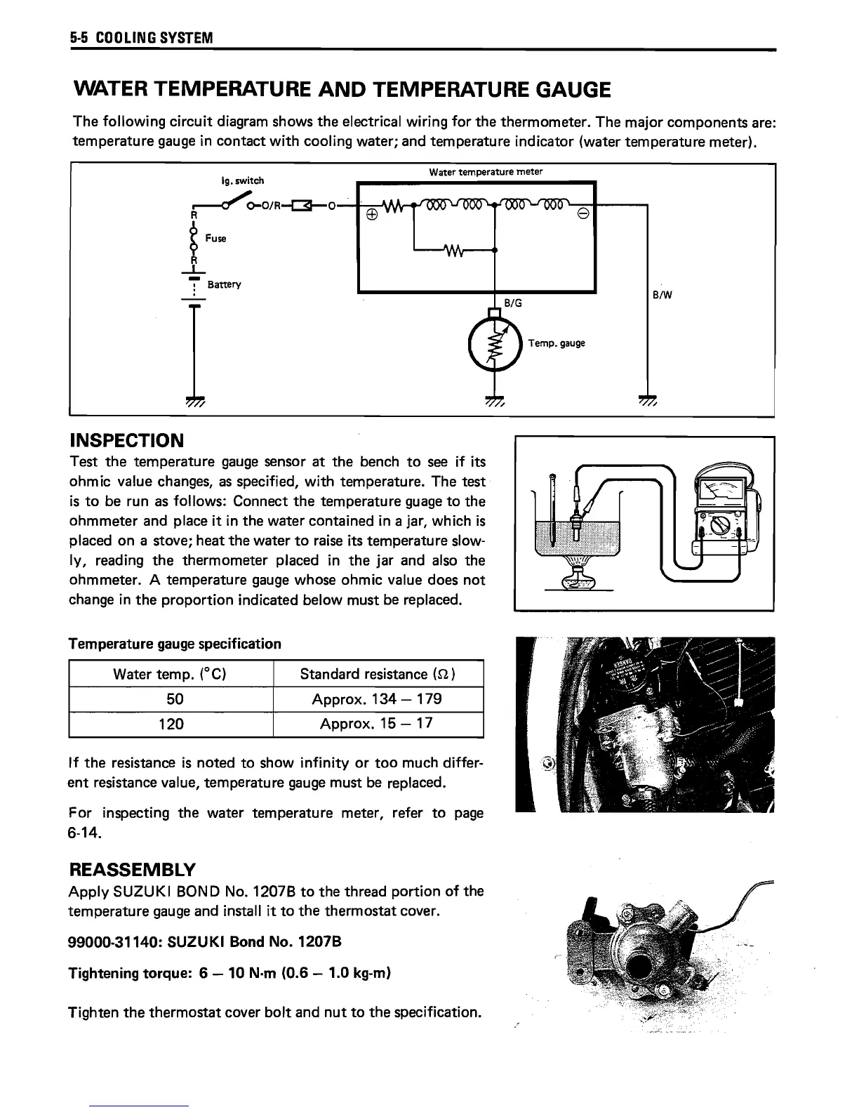
The following circuit diagram shows
the
electrical wiring for the thermometer. The major components are:
temperature gauge
in
contact with cooling water; and temperature indicator (water temperature meter).
Ig.
switch
~~O/R~O-~EB~II'tt-<
...
Water temperature
meter
t Fuse
R
~
:-
Battery
INSPECTION
Test
the
temperature gauge sensor
at
the
bench
to
see if its
ohmic value changes, as specified, with temperature. The test
is
to
be run as follows: Connect
the
temperature guage
to
the
ohmmeter
and place
it
in the water contained in a jar, which
is
placed on a stove; heat
the
water
to
raise its temperature slow-
Iy, reading
the
thermometer placed
in
the
jar and also the
ohmmeter. A temperature gauge whose ohmic value does
not
change
in
the
proportion indicated below must be replaced.
Temperature gauge specification
Water temp.
(0
Cl
Standard resistance
(n)
50
Approx.
134
- 179
120
Approx. 15 - 17
If
the
resistance
is
noted
to
show infinity
or
too
much differ-
ent
resistance value, temperature gauge must be replaced.
For inspecting
the
water temperature meter, refer
to
page
6-14.
REASSEMBLY
Apply SUZUKI BOND
No.
1207B
to
the
thread portion
of
the
temperature gauge and install it
to
the
thermostat cover.
99000-31140: SUZUKI Bond No. 1207B
Tightening
torque:
6 - 10 N·m (0.6 - 1.0 kg-m)
Tighten
the
thermostat
cover bolt and
nut
to
the
specification.
e
Temp.
gauge
B/W
 Loading...