6·13
ELECTRICAL
SYSTEM
WATER TEMPERATURE METER
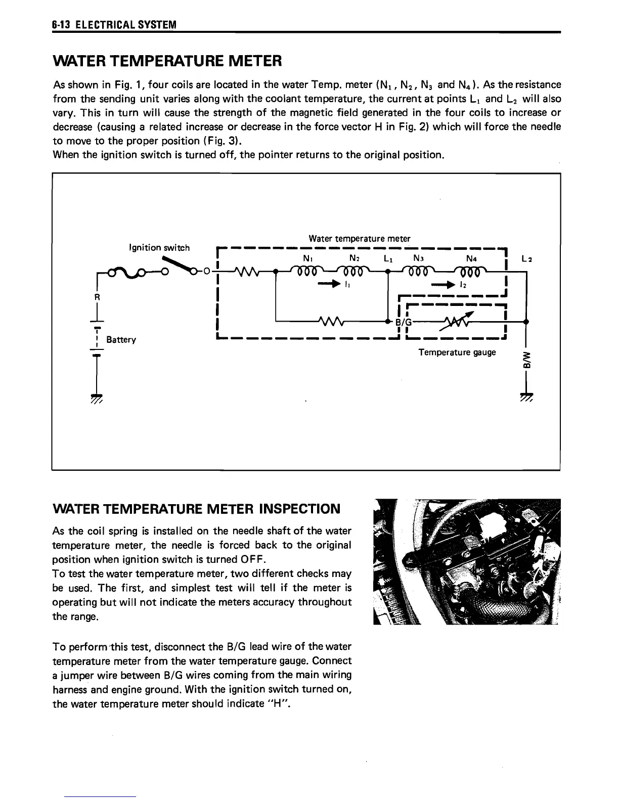
As
shown
in
Fig. 1,
four
coils are located
in
the
water Temp. meter
(NI,
N
2
,
N3
and N
4
).
As
the
resistance
from
the
sending unit varies along with
the
coolant temperature,
the
current
at
points
Ll
and
L2
will also
vary. This in
turn
will cause
the
strength
of
the
magnetic field generated
in
the
four coils
to
increase
or
decrease (causing a related increase
or
decrease in
the
force vector H in Fig. 2) which will force
the
needle
to
move
to
the
proper position (Fig. 3).
When
the
ignition switch
is
turned off,
the
pointer returns
to
the
original position.
Water temperature meter
Ignition switch
r------------------,
~
I
NI
N2
LI
N3 N4
I
~
0 I
-+11
--.12
I
R I
,...------.1
1
I
Ir-----~
I
~f:
L..
__________
~
'--
_____
..
,.
: Battery
I
WATER TEMPERATURE METER INSPECTION
As
the
coil spring
is
installed on
the
needle shaft
of
the
water
temperature meter,
the
needle
is
forced back
to
the
original
position when ignition switch
is
turned OFF.
To
test
the
water temperature meter,
two
different checks may
be used.
The
first, and simplest
test
will tell if
the
meter
is
operating
but
will
not
indicate
the
meters accuracy
throughout
the
range.
To
perform -this test, disconnect
the
BIG
lead wire
of
the
water
temperature meter from
the
water temperature gauge. Connect
a jumper wire between
BIG
wires coming from
the
main wiring
harness and engine ground. With
the
ignition switch
turned
on,
the
water temperature meter should indicate
"H".
Temperature gauge
 Loading...