9·13
RGV250L
('90·MODEL)
INSPECTION
IGNITION
SYSTEM
AND
EXHAUST
VALVE
OPERATION
CHECK
This section explains the checking procedure
for
the total
ignition system and exhaust valve operation using the ignitor
checker. This checking
can
be done
with
the engine on the
machine.
09931·64410:
Ignitor
checker
WIRING
PROCEDURE:
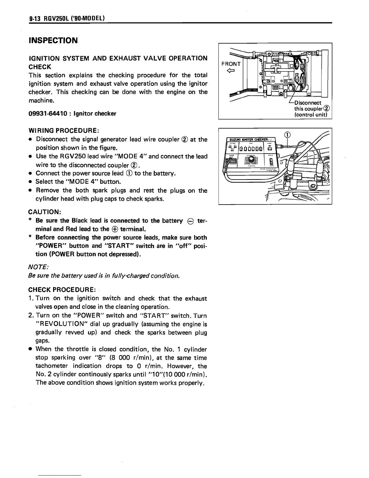
• Disconnect the signal generator
lead
wire coupler ® at the
position shown in the figure.
•
Use
the RGV250
lead
wire
"MODE
4"
and connect the lead
wire
to
the disconnected coupler ®.
• Connect the power source lead
CD
to
the battery.
• Select the
"MODE
4"
button.
• Remove the both spark plugs and rest the plugs on the
cylinder head
with
plug
caps
to
check sparks.
CAUTION:
*
Be
sure
the Black
lead
is
connected
to
the battery 8 ter·
minal and Red lead
to
the
ffi
terminal.
* Before connecting the power source
leads,
make
sure
both
"POWER"
button
and
"START"
switch
are
in
"off"
posi·
tion
(POWER
button
not
depressed).
NOTE:
Be
sure the
battery
used
is
in fu/ly-charged condition.
CHECK PROCEDURE:
1.
Turn
on the ignition switch and check
that
the exhaust
valves open and close in the cleaning operation.
2. Turn on the
"POWER"
switch and
"START"
switch. Turn
"REVOLUTION"
dial up gradually (assuming the engine
is
gradually revved up)
and
check the sparks between plug
gaps.
•
When
the
throttle
is
closed condition, the No. 1 cylinder
stop sparking over
"8"
(8 000
r/min),
at the
same
time
tachometer indication drops
to
0
r/min.
However, the
No. 2 cylinder continously sparks
until
"10"(10000
r/minl.
The above condition
shows
ignition system works properly.
CD
SUZUKI
IGNITER
CHECKER-
.•
isconnect
this
coupler®
(control unit)

 Loading...