6-11
ELECTRICAL
SYSTEM
INSPECTION
EXHAUST
VALVE
OPERATION
• Refer
to
page
3-8.
• Start the engine
and
increase the engine r/min
to
check the
exhaust valve operation.
Exhaust valve Engine r/min
Close
~
Open
8 000 - 8 500
r/min
Open
~
Close
8 500 - 8 000
r/min
•
If
the exhaust valve
does
not
operate
at
the specified r/min,
inspect the individual parts
for
any defect.
ACTUATOR
PULLEY
•
For
removal procedure, refer
to
page
3-8.
• Check
the
actuator resistance values.
Tester connected
to:
Resistance
Tester
range
R-B
1 - 20 n
x1n
O-V
4-
6
kn
xkn
NOTE:
Do
not
move the pulley at the this time.
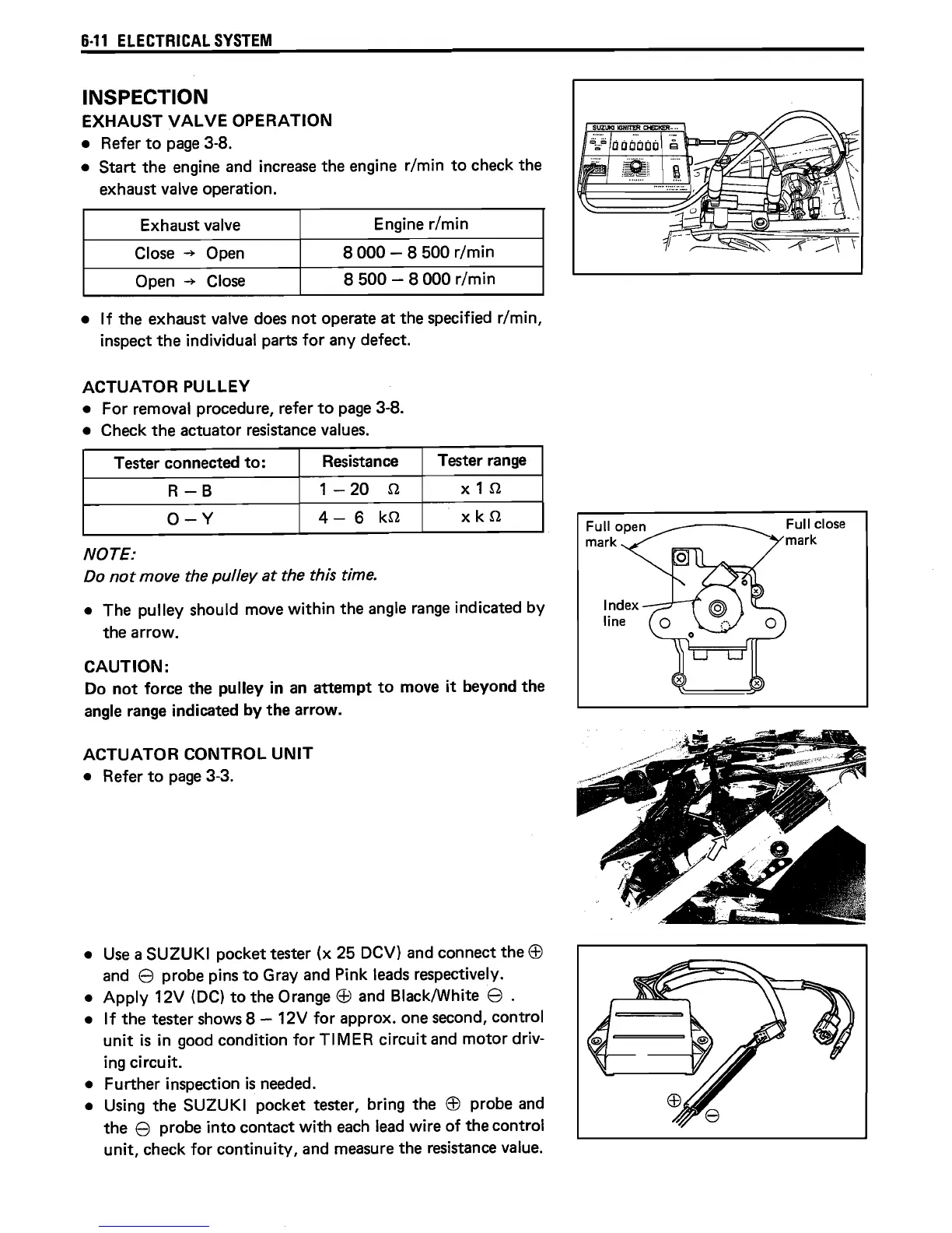
• The pulley should move
within
the angle
range
indicated by
the arrow.
CAUTION:
Do
not
force the pulley in
an
attempt
to
move
it
beyond the
angle range indicated by the arrow.
ACTUATOR
CONTROL
UNIT
• Refer
to
page
3-3.
•
Use
a SUZUKI pocket tester (x 25 DCV) and connect the
EB
and e probe pins
to
Gray and Pink
leads
respectively.
•
Apply
12V
(DC)
to
the Orange
EB
and BlacklWhite e .
•
If
the tester shows 8 - 12V
for
approx. one second, control
unit
is
in good condition
for
TIMER
circuit
and
motor
driv-
ing circuit.
• Further inspection
is
needed.
• Using the SUZUKI pocket tester, bring the
EB
probe
and
the e probe
into
contact
with
each
lead
wire
of
the control
unit,
check
for
continuity,
and measure the resistance value.
Index
line
Full close
mark
 Loading...