6-7
ELECTRICAL
SYSTEM
PICK-UP COIL
• Remove
the
Lower fairing and disconnect
the
pick-up coil
lead coupler.
• Using a pocket tester
(x
100
n)
measure
the
resistance
between Black and Brown lead wires. If the resistance
is
infinity
or
less
than the specification,
the
pick-up coil must
be replaced.
09900-25002: Pocket tester
• Signal generator
Tester connected
to:
Resistance
Tester range
R-W
20
- 200 n
x 10 n
B -
Br
20
- 200 n
x 10 n
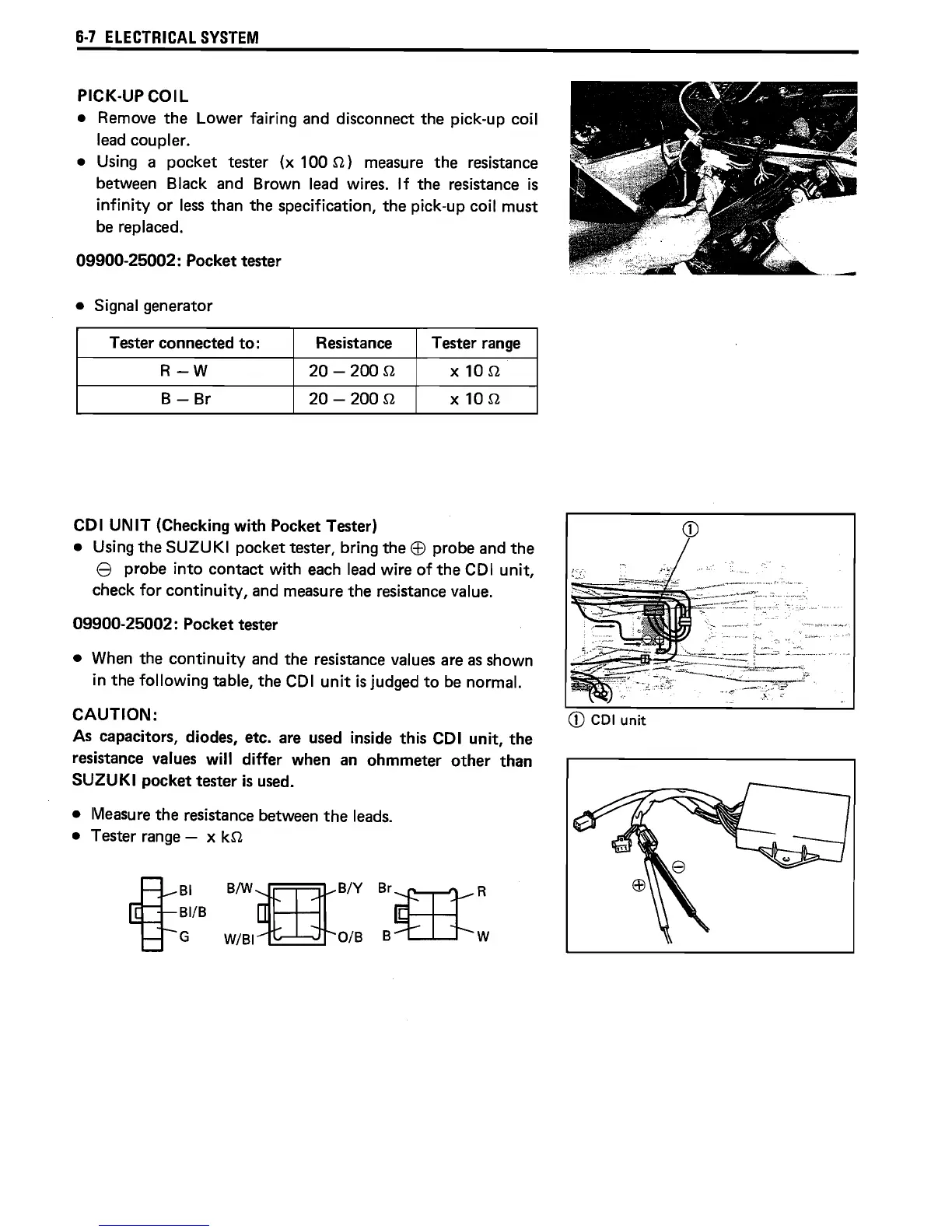
COl UNIT (Checking with Pocket Tester)
• Using
the
SUZUKI pocket tester, bring
the
EB
probe and
the
e probe into contact with each lead wire
of
the
COl
unit,
check for continuity, and measure
the
resistance value.
09900-25002: Pocket tester
• When the continuity and
the
resistance values are
as
shown
in
the following table,
the
COl
unit
is
judged
to
be normal.
CAUTION:
As
capacitors, diodes, etc. are used inside this COl unit,
the
resistance values will differ when an ohmmeter
other
than
SUZUKI pocket tester
is
used.
• Measure
the
resistance between
the
leads.
• Tester range - x
kn
i
BI
BIWtIJBIY
BI/B
G
W/BI
O/B
Br;;f'l1-R
B~W
 Loading...