6-5
ELECTRICAL
SYSTEM
IGNITION SYSTEM
Signal
generator
Neutral
indicator
light
·0!:"'Y
DESCRIPTION
L
Neutral
;nd;cato, I
,;ght ..,;'ch •
COl
unit
IBIY
Ignition coil
Spark
plug
G
B/W
r;d'stand
switch
,
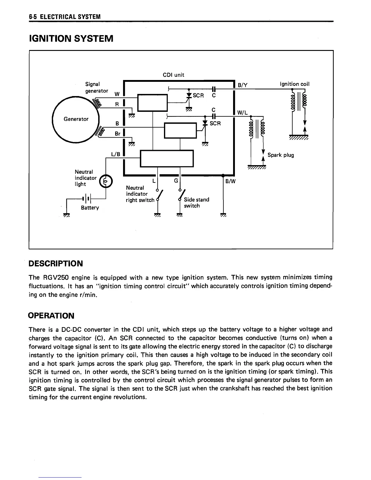
The RGV250 engine
is
equipped
with
a new type ignition system. This new system minimizes timing
fluctuations.
It
has
an
"ignition
timing control
circuit"
which accurately controls ignition
timing
depend-
ing on the engine r/min.
OPERATION
There
is
a DC-DC converter in the COl
unit,
which steps up the battery voltage
to
a higher voltage and
charges the capacitor (C). An
SCR
connected
to
the capacitor becomes conductive (turns on) when a
forward voltage signal
is
sent
to
its gate allowing the electric energy stored in the capacitor
(C)
to
discharge
instantly
to
the ignition primary coil. This then
causes
a high voltage
to
be
induced in the secondary coil
and a
hot
spark jumps
across
the spark plug
gap.
Therefore, the spark in the spark plug occurs when the
SCR
is
turned on. In other words, the SCR's being turned on
is
the ignition timing (or spark timing). This
ignition
timing
is
controlled
by
the control circuit which
processes
the signal generator pulses
to
form
an
SCR
gate signal. The signal
is
then sent
to
the
SCR
just when the crankshaft
has
reached the best ignition
timing
for
the current engine revolutions.
 Loading...