EasyManuals Logo

Suzuki VLR1800 Service Manual

Suzuki VLR1800
624 pages
To Next Page IconTo Next Page
To Previous Page IconTo Previous Page
Page #537 background imageLoading...
Page #537 background image
Manual Transmission: 5B-5
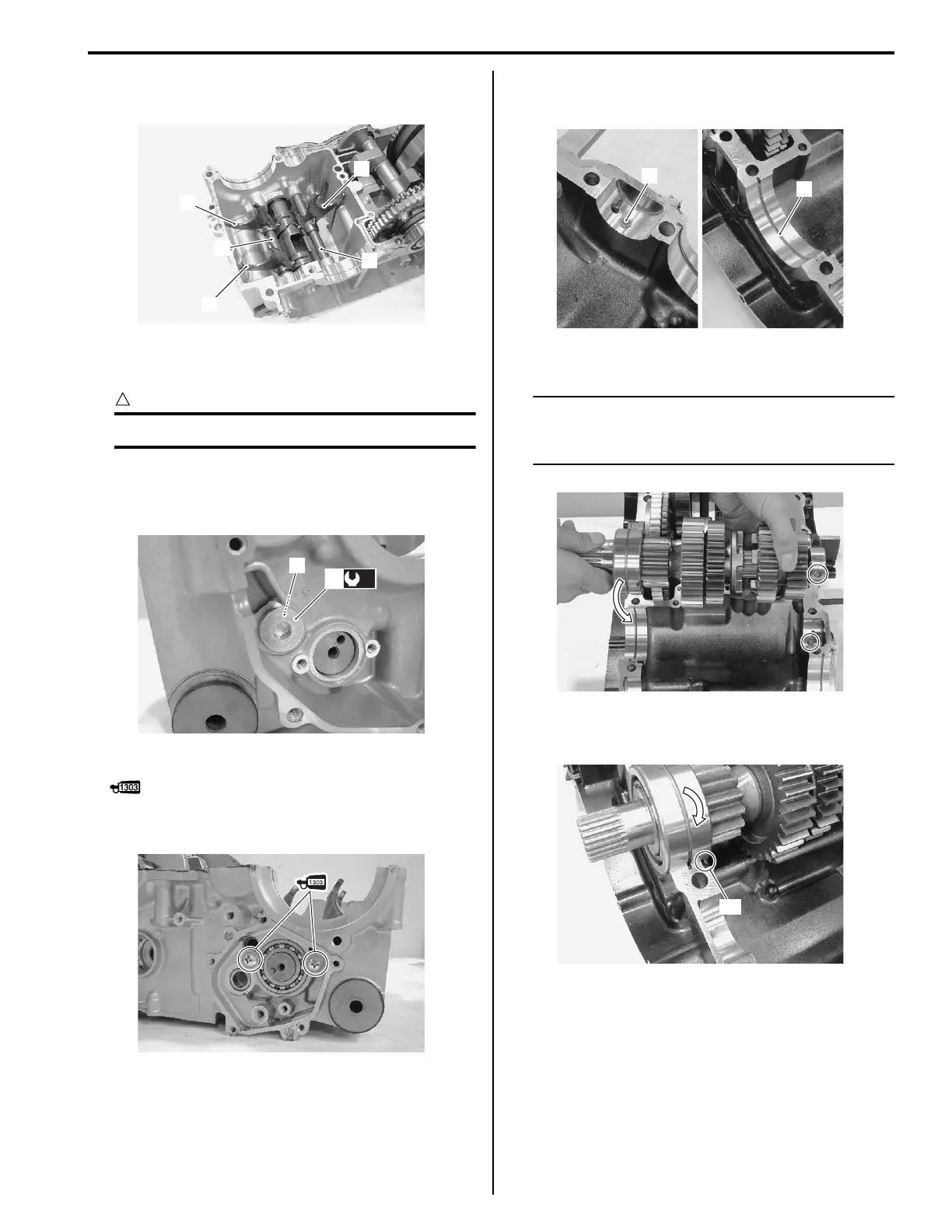
Install the gearshift fork shafts (3) and gearshift forks
(4).
Tighten the shift fork retainer plug (5) to the specified
torque.
CAUTION
!
Replace the gasket (6) with a new one.
Tightening torque
Gearshift fork retainer plug (a): 35 N·m (3.5 kgf-
m, 25.5 lb-ft)
Apply thread lock to the screws and tighten them.
: Thread lock cement 99000–32030
(THREAD LOCK CEMENT SUPER 1303 or
equivalent)
Countershaft Assembly
Install the bearing pin (1) and C-ring (2).
Install the countershaft on the upper crankcase.
NOTE
Align the C-ring with the groove of the
bearing and bearing pin with the indent on
the bearing.
Turn the bearing to install the bearing dowel pin “A” in
the respective position.
3
4
3
4
4
I822H1520012-01
(a)
5
6
I822H1520013-01
I822H1520014-01
1
2
I822H1520015-01
I822H1520016-02
“A”
I822H1520017-01

Table of Contents

Questions and Answers:

Question and Answer IconNeed help?

Do you have a question about the Suzuki VLR1800 and is the answer not in the manual?

Suzuki VLR1800 Specifications

General IconGeneral
ManufacturerSuzuki
ModelVLR1800
Compression Ratio10.5:1
Fuel SystemFuel injection
StarterElectric
Transmission5-speed
CategoryCruiser
Displacement1783 cc
IgnitionElectronic ignition (Transistorized)
Final DriveShaft
Front SuspensionTelescopic, coil spring, oil damped
Rear SuspensionLink type, coil spring, oil damped
Rear BrakesSingle disc
Ground Clearance140 mm
Seat Height705 mm

Related product manuals