Oscilloscope R eference Glitch trigger
Glitch trigger
A glitch trigger occurs when the instrument detects a pulse narrower (or wider) than some specified time.
You can set the instrument to trigger o n glitches of either polarity or to reject glitches of either polarity.
Pattern trigger
A pattern trigger occurs when the inputs to the selected logic function cause the function to become True
or False. When you use a pattern trigger, you define:
The precondition for each logic input: logic high, low, or "don't care"; the logic inputs are the
instrument channels
The Boolean logic function: AND, NAND, OR, or NOR
The condition for triggering: the Boolean function becomes True (logic high) or False (logic low),
and whether the True condition is time qualified
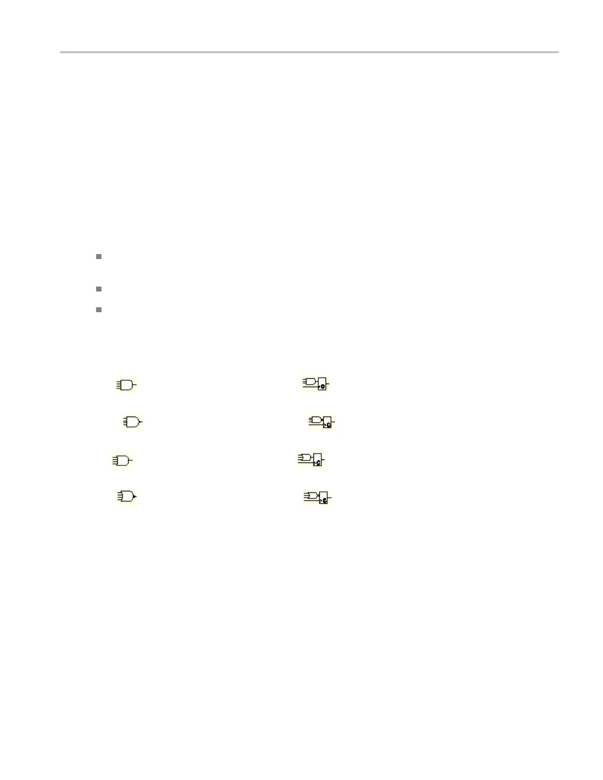
Pattern trigger logic choices are summarized in the next table.
Pattern State Definition
1
,
2
AND
Clocked AND
If all the preconditions selected for
the logic inputs
3
are TRUE, then the
instrument triggers.
NAND
Clocked N AND
If not all of the preconditions selected
for the logic inputs
3
are TRUE, then
the instrument triggers.
OR
Clocked OR
If any of the preconditions selected for
the logic inputs
3
are TRUE, then the
instrument triggers.
NOR
Clocked NOR
If none of the preconditions selected
for the logic inputs
3
are TRUE, then
the instrument triggers.
xxx
1
For state triggers, the definition must be met at the time the clock input changes state
2
Th
edefinitions given here are correct for the Goes TRUE setting in the Trigger When menu. If that menu is set to Goes False, swap the definition for
AND with that for NAND and for OR with NOR for both pattern and state types.
3
The logic inputs are channels 1, 2, 3, and 4 when using Pattern triggers. For State triggers, channel 4 becomes the clock input, leaving
the remaining channels as logic inputs.
DSA/DPO70000D, MSO/DPO/DSA70000C, DPO7000C, and MSO/DPO5000 Series 705
 Loading...


