Model 4200A-SCS Prober and External Instrument Control Section 7: Using a Keysight 8110A/8111A Pulse Generator
4200A-913-01 Rev. A December 2020 7-7
The amount of time to delay after receiving the trigger (0 s to 0.999 s)
Sets the pulse rise time (2e-09 s to 0.2 s)
Sets the pulse fall time (2e-09 s to 0.2 s)
Sets the pulse width (3.3e-09 s to 0.999 s)
Sets the period to use if more than one pulse will be triggered; if a single pulse is
output (as opposed to a burst of pulses), this parameter is ignored; (6.65e-09 to
999; 6.65e-09 to 0.999 if there is no PLL option installed in the pulse generator)
The base value of the pulse (−20 V to +20 V); for a pulse with no DC offset,
set this parameter to 0
The amplitude of the pulse as measured from the base value (−20 V to +20 V)
Sets the output impedance of the PGU:
▪ 0: 50 Ω
▪ 1: 1000 Ω
The expected impedance of the load (DUT) (0 to 999 kΩ); if unsure, enter the
maximum value
A flag that determines whether to enable or disable the output relay of the PGU:
▪ 0: Disable the output
▪ 1: Enable the output
Details
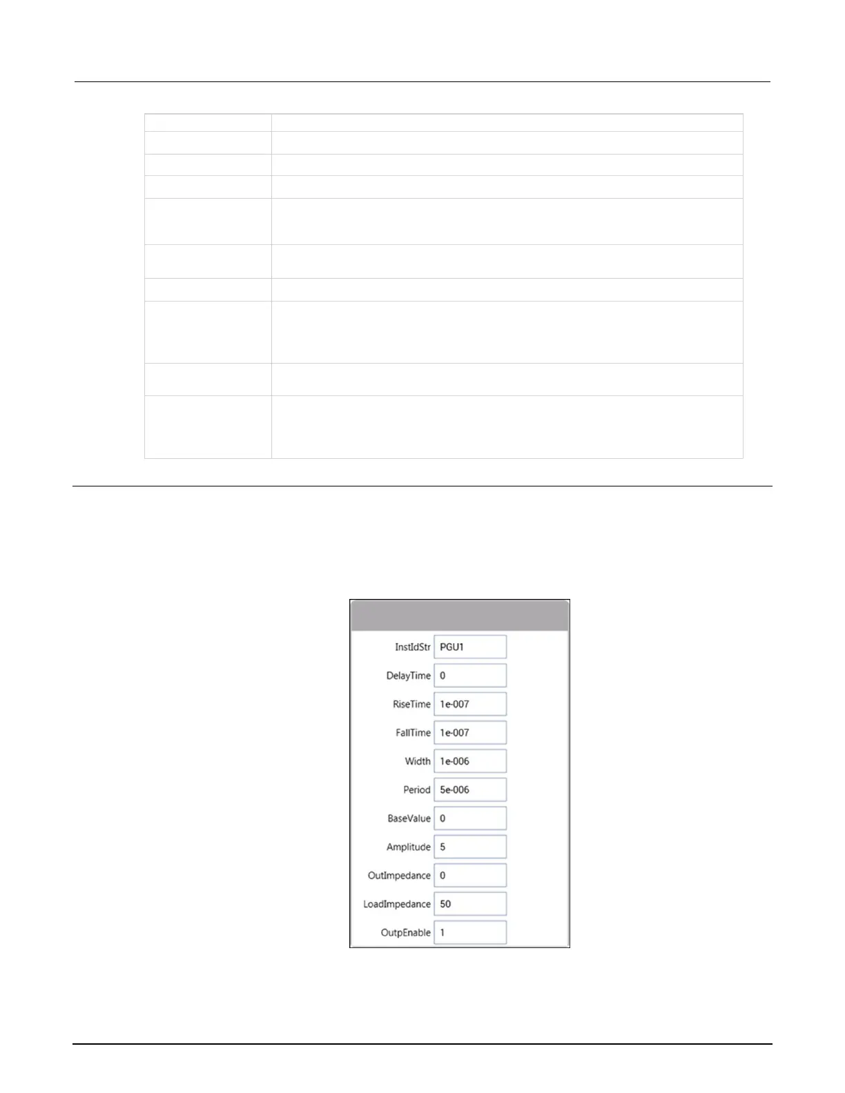
The PguSetup8110 user module defines the pulse timing and voltage settings. Once defined, the
pulse can be triggered using the PguTrigger8110 user module.
The following figure shows the default parameters for pgu1-setup UTM.
Figure 119: PguSetup8110 (pgu1-setup UTM)
The following figure shows the output pulse for the default UTM setup.

 Loading...


