Signal connections
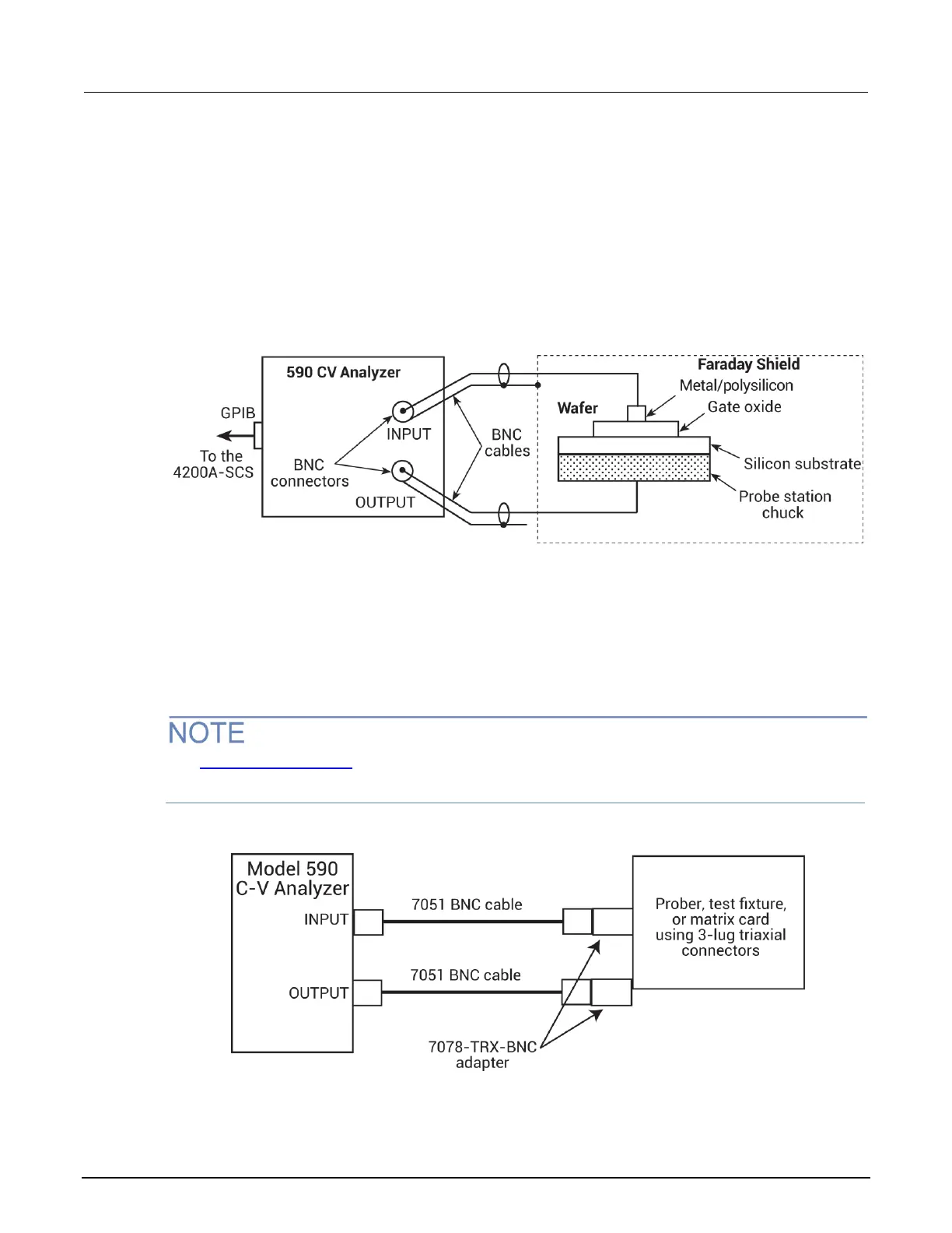
Basic signal connections for the 590 are shown in the following figure.
The center conductors of the BNC connectors are connected to the device under test (DUT). The
outer shield of one of the coaxial cables is typically connected to a Faraday shield. The Model 590
output is typically connected to the wafer backside (or well). The input is typically connected to the
gate of a MOS capacitor.
Figure 48: Basic 590 connections to the DUT
Triaxial connectors
Adapters are required to connect the 590 to equipment (for example, a probe station, test fixture, or
matrix card) that uses triaxial connectors. The 7078-TRX-BNC is a 3-lug triaxial to BNC adapter. As
shown in the following figure, connect the adapters to the 3-slot triaxial connectors and then use a
7051 BNC cable to make the connections to the 590.
See Using Switch Matrices (on page 2-1) for details on using a switch matrix with the 590 C-V
Analyzer.
Figure 49: Connecting the 590 to equipment with triaxial connectors

 Loading...


