Home
Tektronix
Measuring Instruments
Keithley 4200A-SCS
Tektronix Keithley 4200A-SCS User Manual
4
of 1
of 1 rating
324 pages
Give review
Manual
Specs
To Next Page
To Next Page
To Previous Page
To Previous Page
Loading...
Model 4200A-SCS Prober and External Instrument Control
Section
8
:
Set up a probe station
4200A
-913-01 Rev. A December 2020
8-5
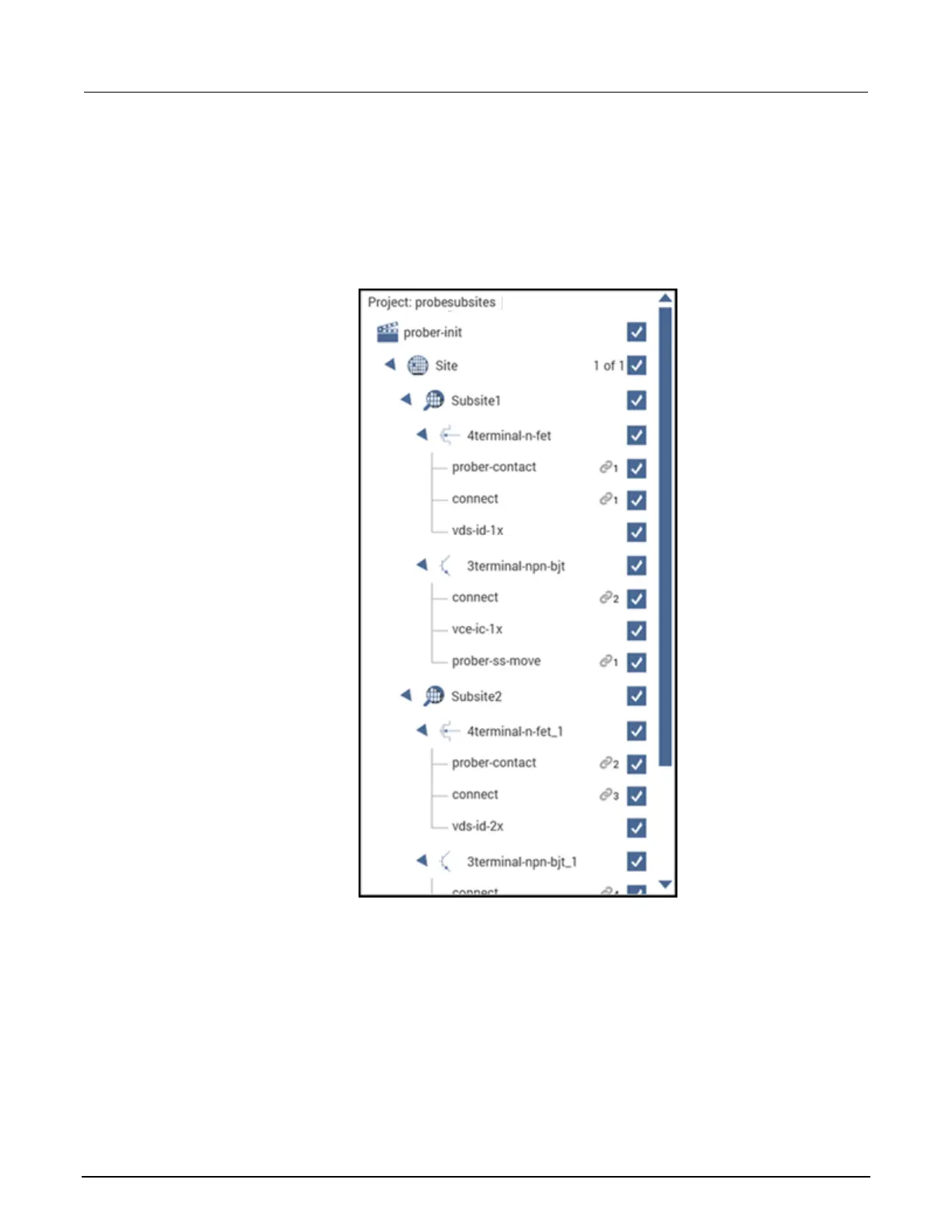
Example test executio
n sequence: probesubsites project
In this example, the
probesu
bsites
projec
t is selected. When you ru
n the test for the si
te, tests are
run for each of the subsit
es.
Figure 123: probe
subsites project t
ree
Understanding site coordinate information
The next topics desc
ribe the reference s
ite, probe sites
, and chuck movement.
186
188
Table of Contents
Default Chapter
6
Table of Contents
6
Introduction
12
Using Switch Matrices
13
Typical Test Systems Using a Switch Matrix
13
Matrix Card Types
14
Switch Matrix Mainframes
19
Switch Matrix Connections
19
Typical SMU Matrix Card Connections
19
Typical Preamplifier Matrix Card Connections
21
Typical CVU Matrix Card Connections
22
Typical CVU Test Connections to a DUT
23
Connection Scheme Settings
25
Row-Column or Instrument Card Settings
25
Switch Matrix Control
28
Signal Paths to a DUT
29
4200A-SCS Signal Paths
29
C-V Analyzer Signal Paths
32
Keysight Model 8110A Pulse Generator Signal Path
35
Use Kcon to Add a Switch Matrix to the System
35
Step 1. Exit Clarius and Open Kcon
36
Step 2. Add a Test Fixture or Probe Station
36
Step 3. Add Switching System Mainframe
38
Step 4. Set GPIB Address
39
Step 5. Configure the Instrument Connection Scheme
40
Step 6. Assign Switch Cards to Mainframe Slots
40
Step 7. Set Matrix Card Properties
41
Step 8. Save Configuration
42
Step 9. Close Kcon and Open Clarius
42
Switch Matrix Control Example
42
Set up and Run a Switch Matrix in Clarius
43
Matrixulib User Library
44
Connectpins User Module
44
Configure and Use a Series 700 Switching System
47
Introduction
47
Equipment Required
48
Device Connections
48
Connect the 7072 to the DUT
49
Connect the 4200A-SCS to the 7072
50
Update the Switch Configuration in Kcon
51
Set up the Measurements in Clarius
56
Create a New Project
56
Add a Device
57
Add the Connectpins Action
57
Configure the Connectpins Action
58
Search for and Add Existing Tests from the Test Library
61
Run the Project and View the Tests
62
Using a Model 590 C-V Analyzer
63
Introduction
63
Capacitance Measurement Tests
64
Connections
64
Signal Connections
65
Triaxial Connectors
65
GPIB Connections
66
Cable Compensation
66
Cable Compensation User Modules
67
Using Kcon to Add 590 C-V Analyzer to System
67
Model 590 Test Examples
68
Cable Compensation Example
68
C-V Sweep Example
72
Ki590Ulib User Library
74
Cablecompensate590 User Module
75
Cmeas590 User Module
77
Ctsweep590 User Module
80
Cvpulsesweep590 User Module
83
Cvsweep590 User Module
88
Displaycablecompcaps590 User Module
92
Loadcablecorrectionconstants
93
Savecablecompcaps590 User Module
94
Using a Keysight 4284/4980A LCR Meter
97
Introduction
97
C-V Measurement Basics
97
Capacitance Measurement Tests
98
Signal Connections
99
GPIB Connections
101
Using Kcon to Add a Keysight LCR Meter to the System
102
Model 4284A or 4980A C-V Sweep Test Example
102
Hp4284Ulib User Library
104
Cvsweep4284 User Module
104
Cmeas4284 User Module
107
Using a Model 82 C-V System
110
Capacitance Measurement Tests
110
C-T Measurements
110
Simultaneous C-V Measurements
112
Cable Compensation
113
Cable Compensation User Modules
114
Connections
114
Front-Panel Connections
114
Rear-Panel Connections
115
Make Power and GPIB Connections
116
Using Kcon to Add Model 82 C-V System
117
Model 82 Projects
117
Cable Compensation Tests
117
Capacitance Tests
121
Formulas for Capacitance Tests
128
Choosing the Right Parameters
131
Optimal C-V Measurement Parameters
131
Determining the Optimal Delay Time
133
Correcting Residual Errors
135
Ki82Ulib User Library
137
Abortmodule82
137
Cablecompensate82 User Module
137
Ctsweep82 User Module
140
Displaycablecompcaps82 User Module
143
Qtsweep82 User Module
145
Savecablecompcaps82 User Module
148
Simcvsweep82 User Module
150
Simultaneous C-V Analysis
153
Analysis Methods
153
Basic Device Parameters
154
Doping Profile
161
Interface Trap Density
162
Mobile Ion Charge Concentration
163
Generation Velocity and Generation Lifetime (Zerbst Plot)
166
Constants, Symbols, and Equations Used for Analysis
168
Summary of Analysis Equations
169
References
172
Bibliography of C-V Measurements
172
Articles and Papers
172
Using a Keysight 8110A/8111A Pulse Generator
175
Introduction
175
Pulse Generator Tests
176
Signal Connections
176
GPIB Connections
178
Using Kcon to Add a Keysight Pulse Generator to the System
178
Hp8110Ulib User Library
179
Pguinit8110 User Module
179
Pgusetup8110 User Module
180
Pgutrigger8110 User Module
182
Set up a Probe Station
183
Prober Control Overview
183
Supported Probers
185
PRBGEN User Modules
185
Example Test Execution Sequence: Probesites Project
186
Example Test Execution Sequence: Probesubsites Project
187
Understanding Site Coordinate Information
187
Reference Site (Die)
188
Probe Sites (Die)
189
Chuck Movement
189
PRBGEN User Library
191
Prinit
192
Prchuck
193
Prssmovnxt
194
Prmovnxt
195
Tutorial: Control a Probe Station
196
Test System Connections
197
Kcon Setup
198
Test Flow
198
Using a Cascade Microtech PA200 Prober
201
Cascade Microtech PA200 Prober Software
201
Software Versions
201
Probe Station Configuration
203
Set up Communications
203
Make Connections between the 4200A-SCS and the Prober
203
GPIB Control Connector Terminals
205
Set up Communications on the 4200A-SCS
206
Set up Communications on the Prober
207
Set up Wafer Geometry
211
Create a Site Definition and Define a Probe List
214
Load, Align, and Contact the Wafer
216
Aligning the Wafer
218
Start the Alignment Wizard
218
Verify Wafer Alignment
219
Set the Chuck Heights
220
Clarius Probesubsites Project Example
222
Set the Wafer Map
225
Use Kcon to Add a Prober
227
Running Projects
228
Clarius
229
Commands and Error Symbols
230
Using a Micromanipulator 8860 Prober
231
Micromanipulator 8860 Prober Software
231
Software Versions
231
Probe Station Configuration
232
Set up Communications
232
Set up Wafer Geometry
236
Create a Site Definition and Define a Probe List
238
Load, Align, and Contact the Wafer
239
Probesites Clarius Project Example
248
Set Spline Pattern (Optional)
249
Use Kcon to Add a Prober
251
Clarius
252
Probesubsites Clarius Project Example
253
Use Kcon to Add a Prober
255
Clarius
256
Commands and Error Symbols
258
Using a Manual or Fake Prober
259
Using a Manual or Fake Prober Software
259
Manual Prober Overview
259
Fake Prober Overview
260
Modifying the Prober Configuration File
261
Probesites Clarius Project Example
263
Use Kcon to Add a Prober
263
Clarius
264
Probesubsites Clarius Project Example
265
Use Kcon to Add a Prober
265
Clarius
267
Using a Cascade Summit-12000 Prober
268
Cascade Summit 12000 Prober Software
268
Software Version
268
Probe Station Configuration
268
Set up Communications
269
Set up Wafer Geometry
275
Create a Site Definition and Define a Probe List
279
Load, Align, and Contact the Wafer
282
Probesites Clarius Project Example
287
Use Kcon to Add a Prober
287
Clarius
289
Probesubsites Clarius Project Example
290
Nucleus UI Prober Control Software
290
Use Kcon to Add a Prober
293
Clarius
294
Commands and Error Symbols
295
Using a Signatone CM500 Prober
296
Signatone CM500 Prober Software
296
Software Versions
296
Probe Station Configuration
296
Set up Communications
297
Modify the Prober Configuration File
298
Set up Wafer Geometry
299
Load, Align, and Contact the Wafer
301
Set up Programmed Sites Without a Subsite
305
Set up Programmed Sites with a Subsite
307
Clarius Project Example for Probe Sites
309
Cm500
309
Use Kcon to Add a Prober
309
Probe Station Configuration
309
Clarius Project Example
310
Probesites Clarius Project Example
313
Probesubsites Clarius Project Example
314
Commands and Error Symbols
315
Using an MPI Probe Station
316
MPI Prober Software
316
Software Version
316
Probe Station Configuration
317
Set up Communications
317
Load, Align, and Contact the Wafer
319
Set up Wafer Geometry
319
Create a Site Definition and Define a Probe List
319
Clarius Probesites and Probesubsites Project Example
319
MPI Sentio Setup
319
Use Kcon to Add a Prober
319
Clarius
321
Commands and Error Symbols
323
Other manuals for Tektronix Keithley 4200A-SCS
Setup And Maintenance
76 pages
User Manual
138 pages
Quick Start Guide
16 pages
4
Based on 1 rating
Ask a question
Give review
Questions and Answers:
Need help?
Do you have a question about the Tektronix Keithley 4200A-SCS and is the answer not in the manual?
Ask a question
Tektronix Keithley 4200A-SCS Specifications
General
Brand
Tektronix
Model
Keithley 4200A-SCS
Category
Measuring Instruments
Language
English
Related product manuals
Tektronix KEITHLEY 2450-EC
93 pages
Tektronix Keithley 2601B-PULSE
133 pages
Tektronix KEITHLEY 2600B Series
834 pages
Keithley SourceMeter 2470
84 pages
Keithley SourceMeter 2410
125 pages
KEITHLEY SourceMeter 2600B Series
102 pages
Tektronix 576
251 pages
Tektronix 492
303 pages
Tektronix P6015
26 pages
Tektronix Series
104 pages
Tektronix TCP312
120 pages
Tektronix TriMode P7700 Series
56 pages

 Loading...


