E6582233
F-32
6
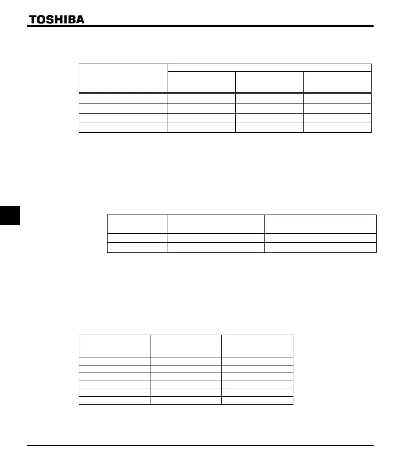
2) Optional dynamic braking resistors
Optional dynamic braking resistors are listed below. All these resistors are 3%ED in operation rate
Inverter type
Brakin
resisto
Type-form Rating
Continuous
regenerative braking
allowable capacit
VFNC3E-4015P to 4022P
PBR-2007
120W-200
90W
VFNC3E-4037P
PBR-4037
120W-160
90W
VFNC3E-4055 to 4075P
PBR7-004W060
440W-60
130W
VFNC3E-4110P
PBR7-008W030
800W-30
270W
Note 1: The data in Rating above refer to the resultant resistance capacities (watts) and resultant resistance
values (Ω).
Note 2: Braking resistors for frequent regenerative braking are optionally available. For more information,
contact your Toshiba distributor.
Note 3: Type-form of “PBR-” indicates the thermal fuse”. Type-form of “PBR7-“ indicates the thermal fuse
and thermal relay.
Note 4: VFNC3E-4055P and VFNC3E-4110P:
Default setting of parameter f308 and f309 is for previous Toshiba breaking resistor PBR3-.
Set parameter
f308 and f309 to following table value.
f308
D
namic brakin
resistance
f309
D
namic brakin
resistor capacit
VFNC3E-4055 60.0 0.44
VFNC3E-4110P 30.0 0.80
VFNC3E-4015P to 4037P and VFNC3E-4075P:
The default setting values of parameter
f308 and f309 are applied to braking resistor option.
3) Minimum resistances of connectable braking resistors
The minimum allowable resistance values of the externally connectable braking resistors are listed in the
table below.
Do not connect braking resistors with smaller resultant resistances than the listed minimum allowable
resistance values.
Inverter rated output
capacity (kW)
Resistance of standard
option
Minimum allowable
resistance
1.5
200
85
2.2
200
67
3.7
160
45
5.5
60
35
7.5
60
34
11
30
27
Note: Be sure to set f308 at the resistance of the dynamic braking resistor connected.
 Loading...


