E6582233
B-7
2 2
Power circuit
Ter mi na l s
mbol Terminal function
Grounding terminal for connecting inverter. There are 3 terminals in total.
R/L1,S/L2,T/L3 400V class: three-phase 380 to 460V-50/60Hz
U/T1,V/T2,W/T3 Connect to a
three-phase induction
motor.
PA/+,PB
Connect to braking resistors.
Chan
e parameters ,,, if necessar
.
The arrangements of power circuit terminals are different from each range.
Refer to section 1.3.3.1) for details.
Note 1: The PA/+ and PB terminals are not provided for VFNC3E-4004P, 4007P models.
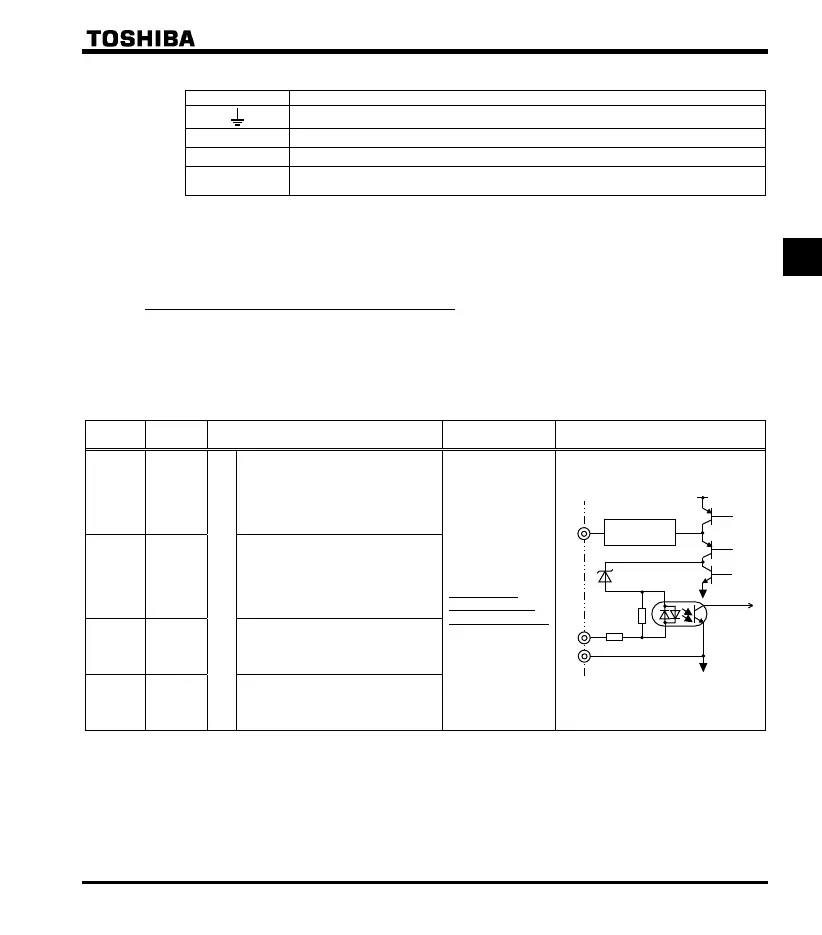
2.3.2 Control circuit terminals
The control circuit terminal board is common to all equipment.
Regarding to the function and specification of each terminal, please refer to the following table.
Refer to section 1.3.3.2) about the arrangement of control circuit terminals.
Control circuit terminals
Terminal
s
mbol
Input /
outpu
Function
Electrical
specifications
Inverter internal circuits
F Input
Multifunction programmable logic input
Shorting across F-CC causes
forward rotation; open causes slow-
down and stop. (When Standby ST
is always ON)
3 different functions can be
assi
ned.
No voltage
logic input
24Vdc-5mA or less
*Sink/Source
selectable using
parameter
(In case of sink
logic is the left)
R Input
Shorting across R-CC causes
reverse rotation; open causes slow-
down and stop. (When Standby ST
is always ON)
3 different functions can be
assi
ned.
S1 Input
Shorting across S1-CC causes
preset speed operation.
2 different functions can be
assi
ned.
S2 Input
Shorting across S2-CC causes
preset speed operation.
2 different functions can be
assi
ned.
CC
P24
F
R
S1
S2
3.65k
+24V
OFF:
External
24V
ON:
Sink
ON:
Source
680
Over current
protection
 Loading...


