E6582233
G-2
7
7.2 Applied operations by an I/O signal (operation from
the terminal block)
7.2.1 Input terminal function
This function is used to send a signal to the input terminal from an external programmable controller to operate or
configure the inverter.
The ability to select from a variety of functions allows for flexible system design.
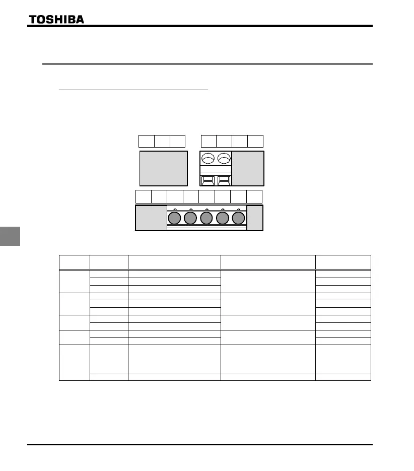
[Control terminal board]
OUT NO CC F R S1 S2 P24
FLA FLB FLC CC VI P5 FM
Settings for the logic input terminal function
Terminal
s
mbol
Title Function Adjustment range Default setting
F
Input terminal selection 1A
F
0-201 Note 1)
2
F
Input terminal selection 1B
F
0
No function
Input terminal selection 1C
F
0
No function
R
Input terminal selection 2A
R
0-201 Note 1)
4
R
Input terminal selection 2B
R
0
No function
Input terminal selection 2C
R
0
No function
S1
Input terminal selection 3A
S1
0-201 Note 1)
10
SS1
Input terminal selection 3B
S1
0
No function
S2
Input terminal selection 4A
S2
0-201 Note 1)
12
SS2
Input terminal selection 4B
S2
0
No function
VI
Analog/logic input
Selection (VI terminal)
0: Voltage signal input (0 - 10 V)
1: Current signal input (4 - 20 mA)
2: Logic input
3: Volta
e si
nal input
0 - 5 V
0
Input terminal selection 5
VI
8-55 Note 3
14
SS3
Note 1) Multiple functions assigned to a single terminal operate simultaneously.
Note 2) In case of setting always active function, assign the menu number to and (always active
function selection).
Note 3) When VI is used for the logic input, always connect a resistor between VI and terminal P24 in sink logic,
between VI and terminal CC in source logic. Refer to section 2.3.2 (page B-12) for details.
 Loading...


