E6582233
C-13
3
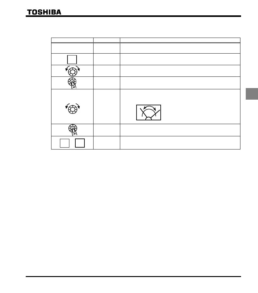
[Example of how to adjustment the FM terminal frequency meter]
* Use the meter's adjustment screw to pre-adjust zero-point.
Operation panel action LED displa
Operation
- .
Displays the output frequency.
(When standard monitor display selection is set to )
The first basic parameter “” (history function) is displayed.
Turn the setting dial to select .
.
Operation frequency can be read by pressing the center of the setting
dial.
.
Turn the setting dial to adjust the meter.
Note that the meter's indicator changes at this time, but the inverter's
display (monitor) does not change.
⇔
Press the center of the setting dial to save the meter's calibrations.
and the frequency are displayed alternately.
+ .
The display returns to its original indications.
(When standard monitor display selection is set to
[Operation frequenc
]
Adjusting the meter in inverter stop state
Adjustment of output current (=1)
If, when adjusting the meter for output current, there are large fluctuations in data during adjustment,
making adjustment difficult, the meter can be adjusted in inverter stop state.
When setting to for fixed output 1 (output current 100% equivalent), a signal of absolute
values will be output (inverter's rated current = 100%). In this state, adjust the meter with the (Meter
adjustment) parameter.
Similarly, if you set to for fixed output 2 (output current 50% equivalent), a signal that is sent
out when half the inverter's rated current is flowing will be output through the FM terminal.
After meter adjustment is ended, set to (output current).
Other adjustments ( = , - , , , )
= : When fixed output 3 (other than the output current) is set, a signal of the the value for
other monitors is fixed at the following values and output through the FM terminal.
100% standard value for each item is the following:
=
0, 2, 12 : Maximum frequency (h)
=
3, 4 : 1.5 times of rated voltage
=
13 : Maximum input value (5V, 10V, or 20mA)
=
18 : Maximum value (1000)
MODE
MODE
MODE
 Loading...


