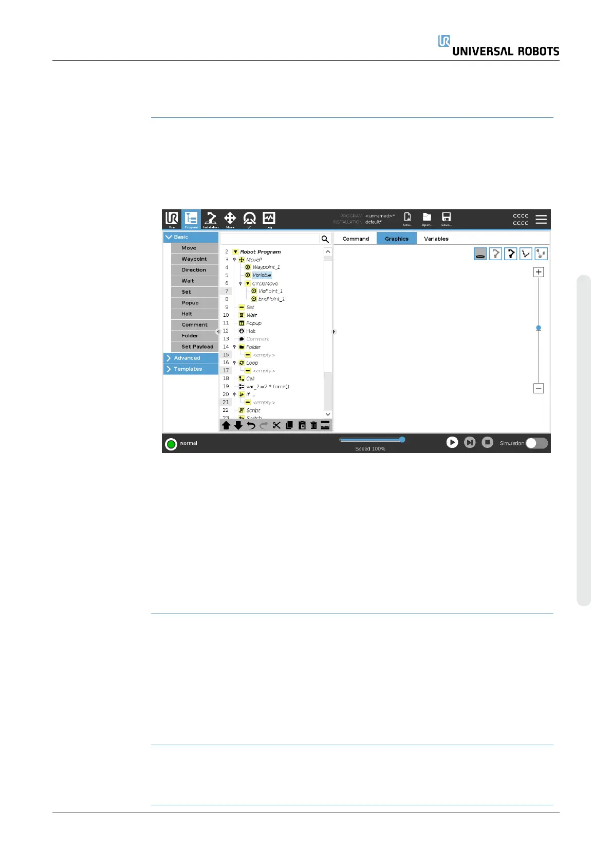
19.2.3. Graphics Tab
Description The Graphics tab in the Program Tab provides a graphical representation of the
running program.
The graphical representation appears in the pane under the Graphics tab on the right
side of the screen.
The buttons in the top-right side of the pane can disable the various graphics in 3D
view.
The 3D drawing of the robot arm shows the current position of the robot arm.
The shadow of the robot arm shows the robot arm's intended path to reach the
waypoint selected in the left hand side of the screen.
The path of the TCP is shown in 3D view:
•
The motion segments are black
•
The blend segments (transitions between motion segments) are green.
•
The green dots specify the positions of the TCP at each of the waypoints in the
program.
Planes A plane is a boundary that limits the movement of the TCP. A plane can also limit the
movement of a tool.
A 3D representation of the plane appears in the pane when the TCP, or tool, comes
close to a plane.
•
You can zoom in to the 3D view to get a better view of the robot arm, TCP or tool.
•
You can use two types planes to limit TCPand tool movement.
Safety Planes Safety planes appear in the 3D view in yellow and black. A small arrow indicates the
side of the plane where the TCP is allowed to be positioned.
User Manual 185 UR10e
Copyright © 2009–2024 by UniversalRobotsA/S. All rights reserved.
 Loading...


