5-20
E
POWR
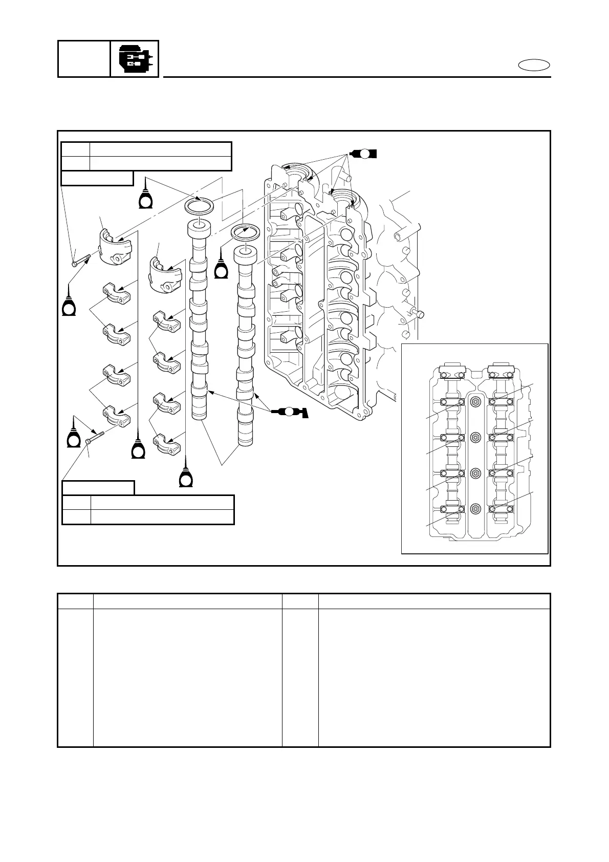
CAMSHAFTS
CAMSHAFTS
EXPLODED DIAGRAM
Å
8 Nm (0.8 m
•
kg, 5.8 ft
•
Ib)1st
17 Nm (1.7 m
•
kg, 12 ft
•
Ib)2nd
2
4
1
6
3
3
5
M
E
E
E
E
7 × 37 mm
8 Nm (0.8 m
•
kg, 5.8 ft
•
Ib)1st
17 Nm (1.7 m
•
kg, 12 ft
•
Ib)2nd
7 × 48 mm
4
4
4
B
H
D
F
G
C
E
A
2
8
4
6
1
09IJ
7
3
5
E
E
GM
4
REMOVAL AND INSTALLATION CHART
Step Procedure/Part name Q’ty Service points
CAMSHAFT REMOVAL
Follow the left “Step” for removal.
Cylinder head cover Refer to “CYLINDER HEAD COVER”.
1 Bolt 16 Refer to the illustration
Å
for the proper
tightening sequence.
2 Bolt 4
3 Camshaft cap 2
4 Camshaft cap 8
5 Oil seal 2
6 Camshaft 2
Reverse the removal steps for installation.
 Loading...