5-35
E
POWR
CRANKSHAFT AND PISTON/
CONNECTING ROD ASSY.
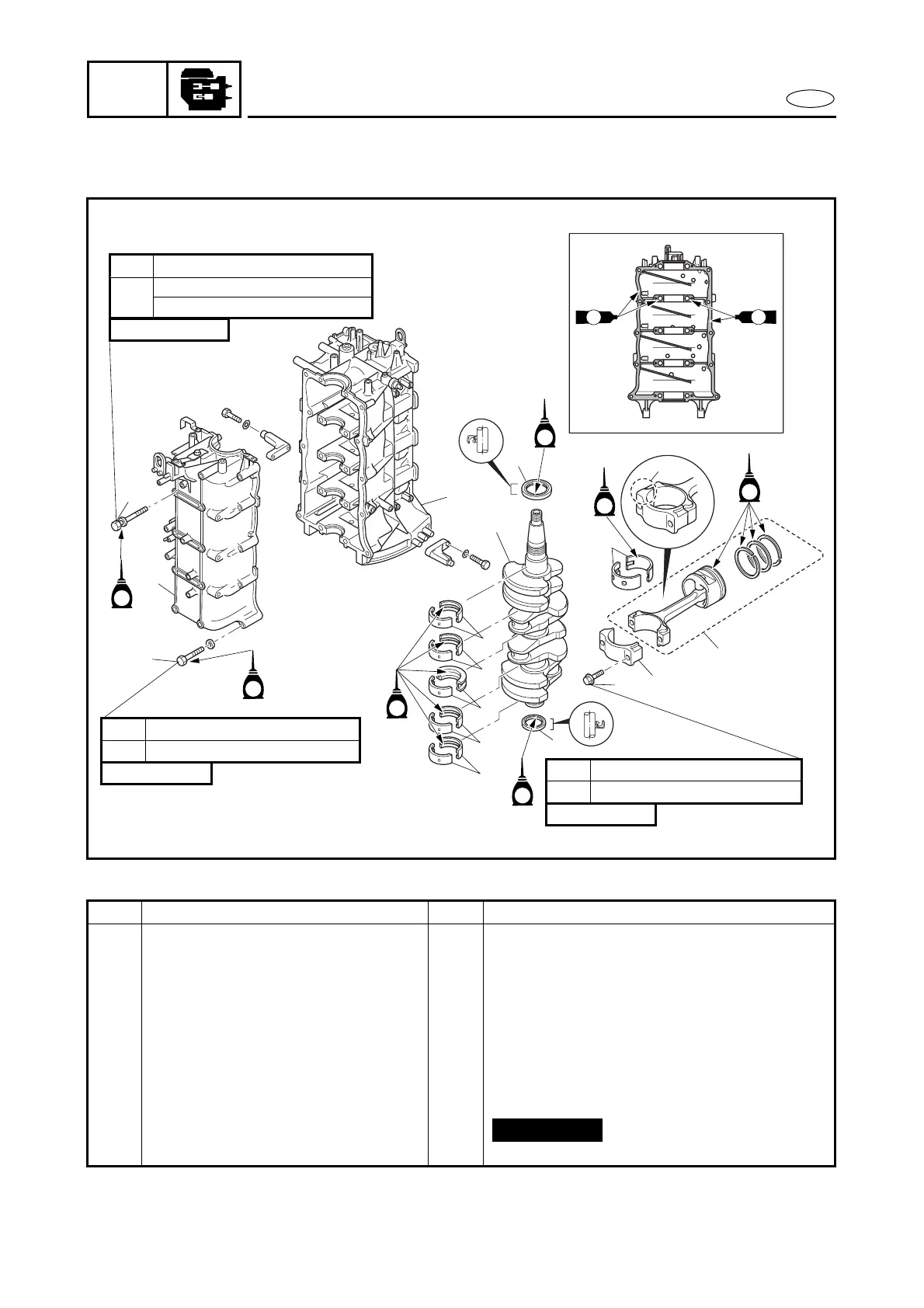
CRANKSHAFT AND PISTON/CONNECTING ROD ASSY.
EXPLODED DIAGRAM
19 Nm (1.9 m
•
kg, 14 ft
•
Ib)1st
60°
2nd
10 × 135 mm
14 Nm (1.4 m
•
kg, 10 ft
•
Ib)1st
28 Nm (2.8 m
•
kg, 20 ft
•
Ib)2nd
8 × 55 mm
8 Nm (0.8 m
•
kg, 5.8 ft
•
Ib)1st
90°2nd
8 × 38 mm
E
E
E
E
E
E
2
3
1
7
11
9
4
8
10
12
6
5
GM
GM
GM
GM
7
7
7
7
E
a
50 Nm (5.0 m
•
kg, 36 ft
•
Ib)*
REMOVAL AND INSTALLATION CHART
* Torque value (for reference only)
Step Procedure/Part name Q’ty Service points
CRANKSHAFT AND PISTON/
CONNECTING ROD ASSY.
REMOVAL
Follow the left “Step” for removal.
Oil filter and exhaust cover Refer to “OIL FILTER AND EXHAUST
COVER”.
1 Bolt 10 Refer to the main-bearing oil clearance
measuring steps for the proper tighten-
ing sequence.
2 Bolt (1.5 mm thread pitch) 10
3 Crankcase 1
4 Connecting rod bolt 8
5 Connecting rod cap 4 Install in the original position.
Not reusable
 Loading...