8-7
–+
ELEC
E
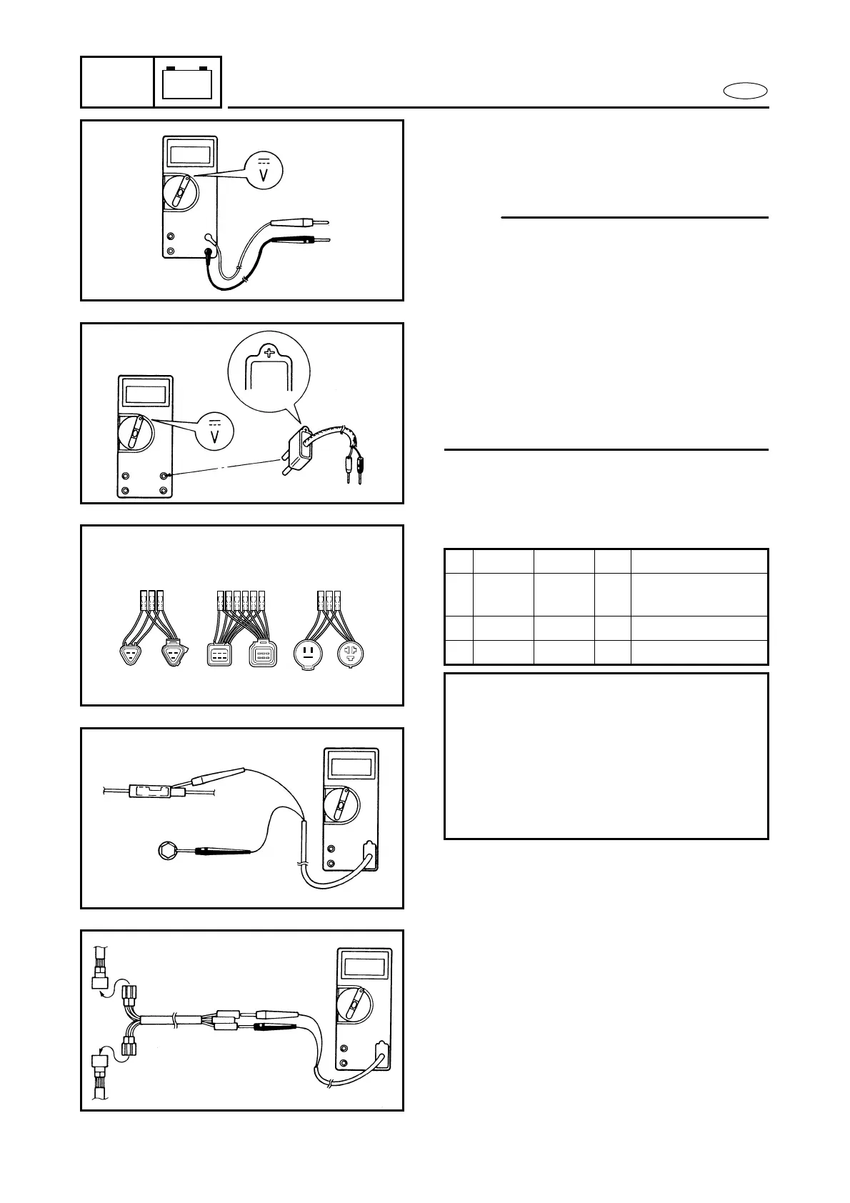
ELECTRICAL ANALYSIS
● When measuring the peak voltage, con-
nect the peak voltage adaptor to the digi-
tal tester and switch the selector to the
DC voltage mode.
NOTE:
● Make sure that the adaptor leads are
properly installed in the digital circuit
tester.
● Make sure that the positive pin (the “+”
mark facing up as shown) on the adaptor
is installed into the positive terminal of
the tester.
● The test harness is needed for the follow-
ing tests.
Å Voltage measurement
ı Peak voltage measurement
Å
ı
Test harness
YB- 90890- Pin Usage
1 06443 06757 3 Throttle position
sensor (TPS)
2 38832 06772 6 Pick-up coil
3 06770 06770 3 Charge coil
Checking steps:
● Disconnect the coupler connections.
● Connect the test harness between the
couplers.
● Connect the tester terminals to the ter-
minals which are being checked.
● Run the engine and observe the mea-
surement.
213
 Loading...


