Parameter List
11
11.10 H: Terminal Functions
YASKAWA SIEPC71061753C GA500 Technical Manual 413
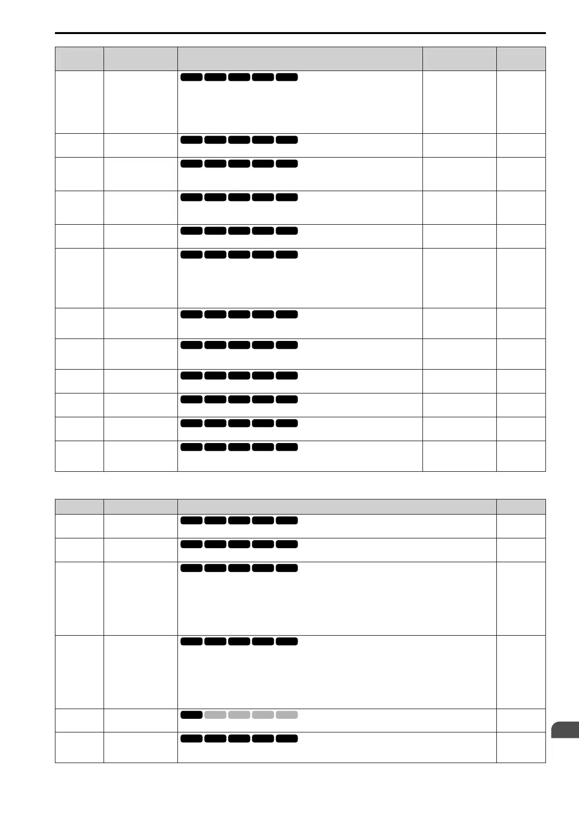
No.
(Hex.)
Name Description
Default
(Range)
Ref.
H3-09
(0417)
Terminal A2 Signal
Level Select
Sets the input signal level for MFAI terminal A2.
0 : 0-10V (LowLim=0)
1 : 0-10V (Without Lower Limit)
2 : 4 to 20 mA
3 : 0 to 20 mA
2
(0 - 3)
670
H3-10
(0418)
Terminal A2 Function
Selection
Sets the function for MFAI terminal A2.
0
(0 - 32)
670
H3-11
(0419)
RUN
Terminal A2 Gain
Setting
Sets the gain of the analog signal input to MFAI terminal A2.
100.0%
(-999.9 - +999.9%)
671
H3-12
(041A)
RUN
Terminal A2 Bias
Setting
Sets the bias of the analog signal input to MFAI terminal A2.
0.0%
(-999.9 - +999.9%)
671
H3-13
(041B)
Analog Input FilterTime
Constant
Sets the time constant for primary delay filters on MFAI terminals.
0.03 s
(0.00 - 2.00 s)
671
H3-14
(041C)
Analog Input Terminal
Enable Sel
Sets the enabled terminal or terminals when H1-xx = C [MFDI Function Select =
Analog Terminal Enable Selection] is ON.
1 : Terminal A1 only
2 : Terminal A2 only
7 : Terminals A1 and A2
7
(1, 2, 7)
671
H3-16
(02F0)
Terminal A1 Offset
Sets the offset level for analog signals input to terminal A1. Usually it is not necessary
to change this setting.
0
(-500 - +500)
671
H3-17
(02F1)
Terminal A2 Offset
Sets the offset level for analog signals input to terminal A2. Usually it is not necessary
to change this setting.
0
(-500 - +500)
672
H3-40
(0B5C)
Mbus Reg 15C1h Input
Function
Sets the MEMOBUS AI1 function.
F
(4 - 2F)
672
H3-41
(0B5F)
Mbus Reg 15C2h Input
Function
Sets the MEMOBUS AI2 function.
F
(4 - 2F)
672
H3-42
(0B62)
Mbus Reg 15C3h Input
Function
Sets the MEMOBUS AI3 function.
F
(4 - 2F)
672
H3-43
(117F)
Mbus Reg Inputs
FilterTime Const
Sets the time constant to apply a primary delay filter to the MEMOBUS analog input
register values.
0.00 s
(0.00 - 2.00 s)
672
■ H3-xx: MFAI Setting Values
Setting Value Function Description Ref.
0 Frequency Reference
The input value from the MFAI terminal set with this function becomes the master frequency reference.
672
1 Frequency Gain
The drive multiplies the analog frequency reference with the input value from the MFAI set with this function.
673
2 Auxiliary Frequency
Reference 1
Sets Reference 2 through multi-step speed reference to enable the command reference (Auxiliary Frequency
Reference 1) from the analog input terminal set here. This value is a percentage where the Maximum Output
Frequency setting is a setting value of 100%.
Note:
Parameter A1-02 [Control Method Selection] selects which parameter is the maximum output frequency.
• A1-02 ≠ 8 [EZOLV]: E1-04 [Maximum Output Frequency]
• A1-02 = 8: E9-02 [Maximum Speed]
673
3 Auxiliary Frequency
Reference 2
Sets Reference 3 through multi-step speed reference to enable the command reference (Auxiliary Frequency
Reference 2) from the analog input terminal set here. This value is a percentage where the Maximum Output
Frequency setting is a setting value of 100%.
Note:
Parameter A1-02 [Control Method Selection] selects which parameter is the maximum output frequency.
• A1-02 ≠ 8 [EZOLV]: E1-04 [Maximum Output Frequency]
• A1-02 = 8: E9-02 [Maximum Speed]
673
4 Output Voltage Bias
Set this parameter to input a bias signal to amplify the output voltage.
673
5 Accel/Decel Time Gain
Enters a signal to adjust the gain used for C1-01 to C1-08 [Acceleration/Deceleration Times 1 to 4] and C1-09
[Fast Stop Time] when the full scale analog signal (10 Vor 20 mA) is 100%.
674

 Loading...


