Electrical Installation
3
3.4 Main Circuit Terminal Block Wiring Procedure
YASKAWA SIEPC71061753C GA500 Technical Manual 87
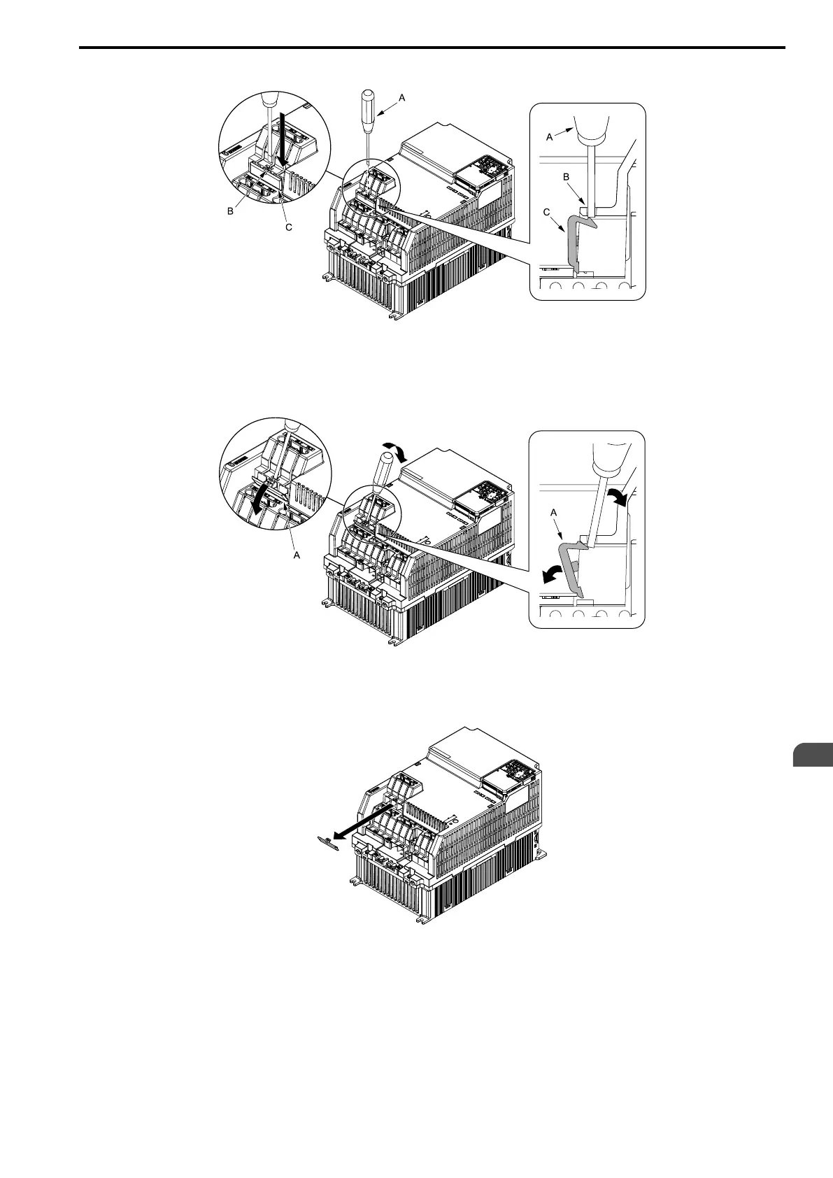
1. Put a slotted screwdriver blade into the slit to push the hook of the IP20 terminal protective cover.
A - Slotted screwdriver
B - Slit
C - IP20 terminal protective cover
Figure 3.32 Put the Screwdriver Blade into the Slit
2. Push up the screwdriver to release the IP20 terminal protective cover.
A - IP20 terminal protective cover
Figure 3.33 Release IP20 terminal protective cover
3. Remove IP20 terminal protective cover.
Figure 3.34 Remove IP20 Terminal Protective Cover
■ Main Circuit Terminal Block Wiring Procedure
When terminals R/L1, S/L2, T/L3, and terminal - have IP20 terminal protective covers, remove the cover on the
terminal where you will wire.
1. Put wires with prepared ends into the main circuit terminal block.
Look through the opening in the drive case to make sure that you correctly installed the wires into the
terminal block.

 Loading...


