3.4 Main Circuit Terminal Block Wiring Procedure
86 YASKAWA SIEPC71061753C GA500 Technical Manual
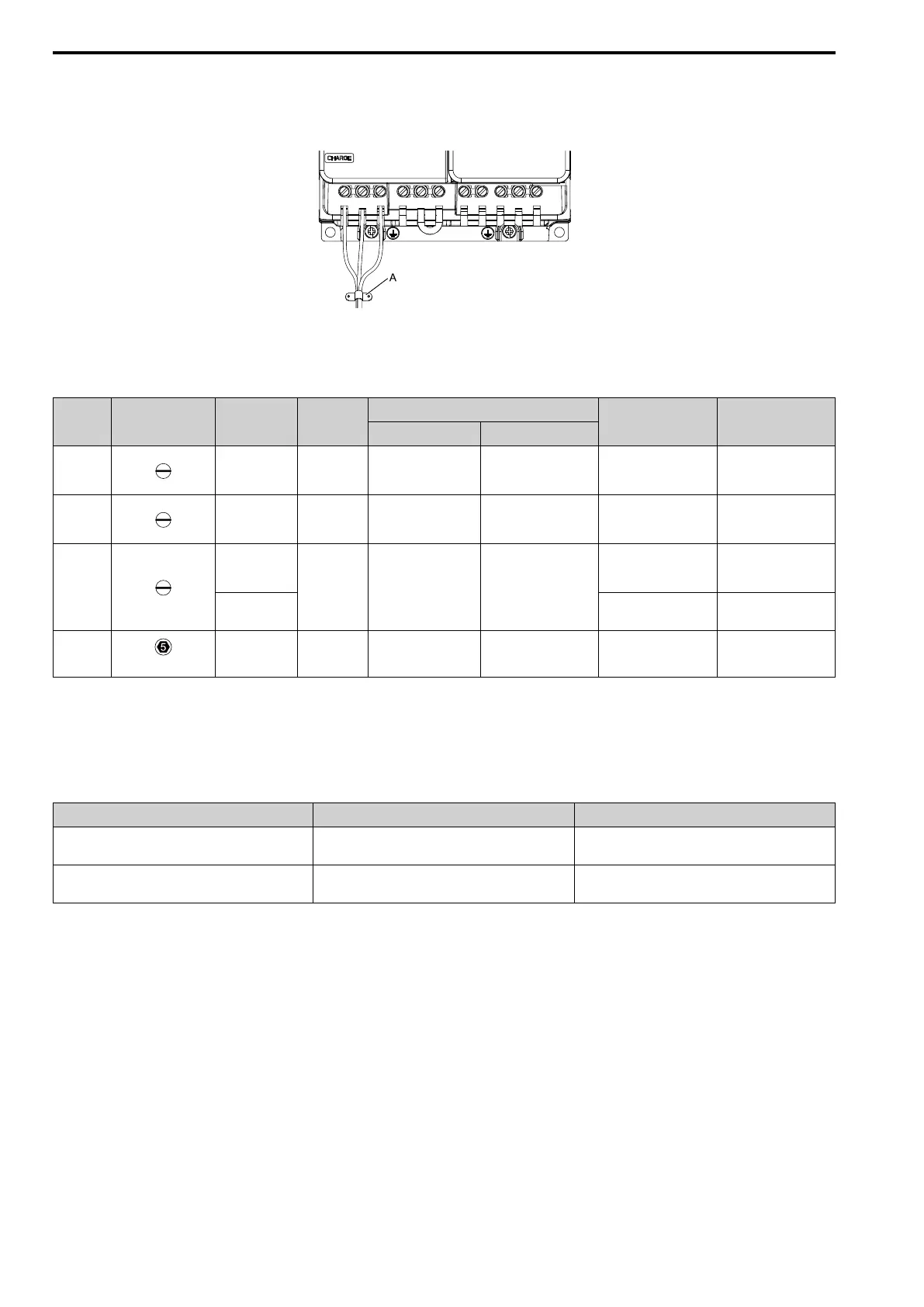
• After you connect the wires to the terminal block, lightly pull on the wires to make sure that they do not come
out of the terminals.
• Do not let strain on the wiring cause damage. Use a strain relief near the wiring to release the tension. Refer to
Figure 3.31 for an example.
A - Cable clamp
Figure 3.31 Strain Relief Example
Table 3.4 Recommended Wiring Tools
Screw
Size
Screw Shape Wire Gauge Adapter
Bit
Torque Driver Model
(Tightening Torque)
Torque Wrench
(Tightening Torque)
Model Manufacturer
M3 - Bit SF-BIT-SL 0,5X3,0-70 PHOENIX CONTACT
TSD-M 1,2NM
(0.3 - 1.2 N∙m
(2.7 - 10.6 lbf∙in))
-
M4 - Bit SF-BIT-SL 1,0X4,0-70 PHOENIX CONTACT
TSD-M 3NM
(1.2 - 3.0 N∙m
(10.6 - 26.6 lbf∙in))
-
M5
*1
≤ 25 mm
2
(AWG 10)
Bit SF-BIT-SL 1,2X6,5-70 PHOENIX CONTACT
TSD-M 3NM
(1.2 - 3.0 N∙m
(10.6 - 26.6 lbf∙in))
-
≥ 30 mm
2
(AWG 8)
-
4.1 - 4.5 N∙m
(36.3 - 39.8 lbf∙in)
*2 *3
M6
(WAF: 5 mm)
- Bit SF-BIT-HEX 5-50 PHOENIX CONTACT -
5 - 9 N∙m
(44.3 - 79.7 lbf∙in)
*2 *3
*1 When you wire drive models 2042, 2056, 4031, 4038, 4044, and 4060, select the correct tools for the wire gauge.
*2 Use 6.35 mm (0.25 in) bit socket holder.
*3 Use a torque wrench that can apply this torque measurement range.
■ Remove IP20 Terminal Protective Cover
These drives have IP20 terminal protective covers. Remove the covers for the application.
Model Terminal R/L1, S/L2, T/L3 Terminal -
2042
4031, 4038
- x
2056, 2070, 2082
4044, 4060
x x

 Loading...


